Method for monitoring a joining process

a technology of mechanical joining and monitoring method, which is applied in the direction of metal-working machine components, metal working apparatus, manufacturing tools, etc., can solve the problems of difficult comparison of joining curves from successive joining processes, and achieve the effect of comparing the relative reference position

Inactive Publication Date: 2014-06-26
NEWFREY
View PDF1 Cites 5 Cited by
  • Summary
  • Abstract
  • Description
  • Claims
  • Application Information

AI Technical Summary

Benefits of technology

[0027]Such a relative reference position can be determined comparatively easily, for example by means of an adjustment pass of the joining tool, in which a reference surface is prepared, onto which the punch is pressed such that it comes

Problems solved by technology

This displacement causes the joining curve to be extended in certain (non-reproducible)

Method used


Image

  • Method for monitoring a joining process
  • Method for monitoring a joining process
  • Method for monitoring a joining process

Examples


Embodiment Construction

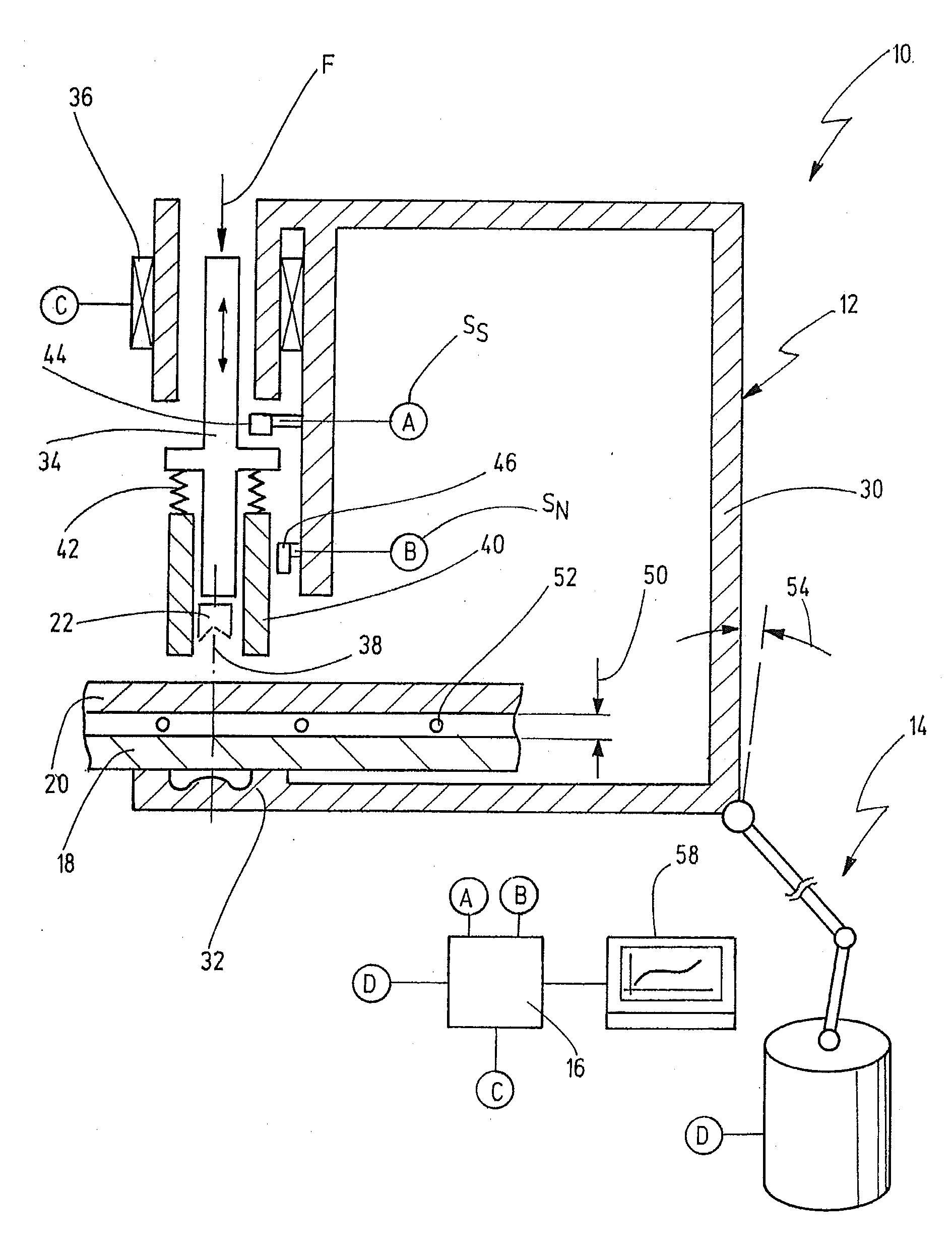
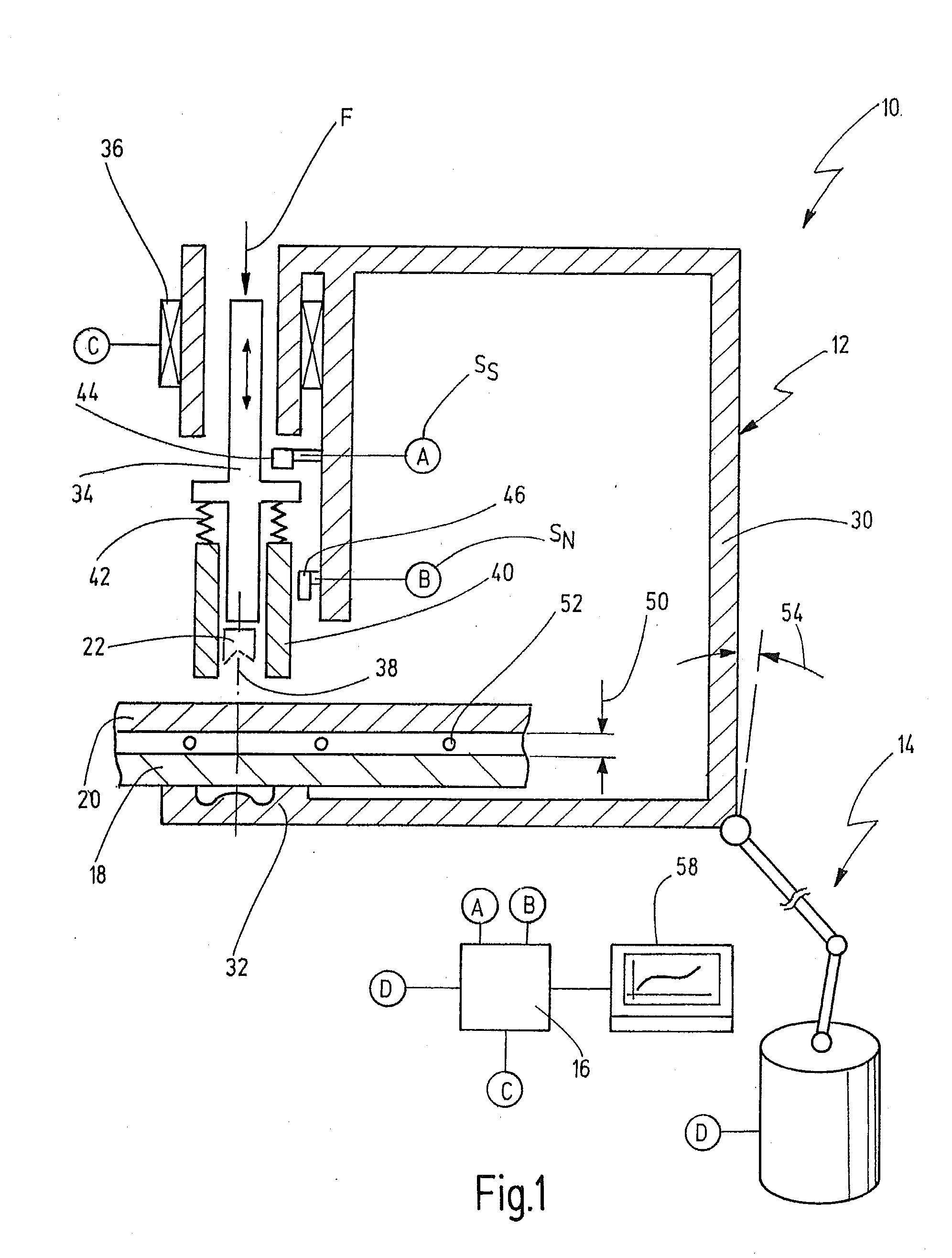
[0040]In FIG. 1, a joining device, in the form of a punch-riveting device, is represented in schematic form and denoted in general by 10. The joining device 10 comprises a joining tool 12, which is fixed to a robot 14 and can be moved two-dimensionally or three-dimensionally in space. Alternatively, the joining tool 12 can also be disposed in a stationary manner.

[0041]The joining device 10 additionally comprises a control device 16, which operates the joining tool 12, and optionally comprises the robot 14.

[0042]The joining device 10 is used for joining together a first workpiece 18 and a second workpiece 20, which can be composed of metal or plastic or composite materials, said joining being effected by means of a punch rivet 22. The punch rivet 22 can be a semi-hollow or a full punch rivet. The joining device 10 can also be used to join together more than two workpieces. The workpieces are preferably plates.

[0043]The joining device 10 is preferably used in the field of body constru...


PUM

PropertyMeasurementUnit
Forceaaaaaaaaaa
Lengthaaaaaaaaaa

Abstract

A method for monitoring a mechanical joining process performed by a joining tool including a frame, a punch that is displaceable on the frame along a joining axis, a die that is mounted on the frame, and a hold-down device, which is mounted in an axially displaceable manner on the punch and biased in a joining direction; and the monitoring method comprises the steps of: starting the joining process; measuring the punch force exerted by the punch; acquiring the relative travel of the punch in relation to the hold-down device; and plotting a joining curve of punch force versus the relative travel.

Description

CROSS-REFERENCE TO RELATED APPLICATION[0001]This application claims priority from German Patent Application No. DE 102012025047.9, filed on Dec. 20, 2012, the disclosure of which is incorporated herein by reference.BACKGROUND OF THE INVENTION[0002]The present invention relates to a method for monitoring a mechanical joining process, in particular a punch-riveting or clinching process, the joining process being performed by means of a joining tool, which has a frame, a punch that is displaceable on the frame along a joining axis, a die that is mounted on the frame, and a hold-down device, which is mounted in an axially displaceable manner on the punch and biased in a joining direction.[0003]Further, the present invention relates to a joining device having a joining tool of the type described above, and having a control device, which is set up to execute the method.[0004]Such a method and such a joining device are known from the document EP 1 228 824 B1.[0005]Known from this document ...

Claims


Application Information

Patent Timeline
IPC IPC(8): B23P19/04
CPCB21D39/031B21J15/025B21J15/285B23P19/04B23P19/062Y10T29/49764Y10T29/53022
Inventor BLOECHER, MICHAELMASAK, JAN
Owner NEWFREY
Why Eureka
Try Eureka