Cryogenic fuel system with auxiliary power provided by boil-off gas

a technology of cryogenic fuel and auxiliary power, which is applied in the direction of fuel systems for specific fuels, machine/engines, containers, etc., can solve the problems of drawbacks of supplying boil-off gas to the atmosphere, increasing pressure within the cryogenic tank, and undesirable effects of supplying boil-off gas

Active Publication Date: 2014-06-26
GENERAL ELECTRIC CO
View PDF10 Cites 11 Cited by
  • Summary
  • Abstract
  • Description
  • Claims
  • Application Information

AI Technical Summary

Benefits of technology

[0003]In another embodiment, a method is provided for providing auxiliary power (e.g., auxiliary power for a vehicle system such as an aircraft). The method includes determining a mode of operation at which a vehicle system is operating, determining an auxiliary energy level, and determining an available boil-off auxiliary energy level that is available from a boil-off gas stream from a cryotank configured to hold a cryogenic fluid. The method also includes operating a boil-off auxiliary energy module based on the mode of operation, the auxiliary energy level, and the available boil-off auxiliary energy level. The boil-off auxiliary energy module is configured to utilize the boil-off gas stream to provide energy to one or more auxiliary components of the vehicle system.

Problems solved by technology

As ambient temperature increases, increasing amounts of LNG within the tank may evaporate as a boil-off gas, creating increasing pressure within the cryogenic tank.
However, venting the boil-off gas to the atmosphere has drawbacks and undesirable effects.

Method used


Image

  • Cryogenic fuel system with auxiliary power provided by boil-off gas
  • Cryogenic fuel system with auxiliary power provided by boil-off gas
  • Cryogenic fuel system with auxiliary power provided by boil-off gas

Examples


Embodiment Construction

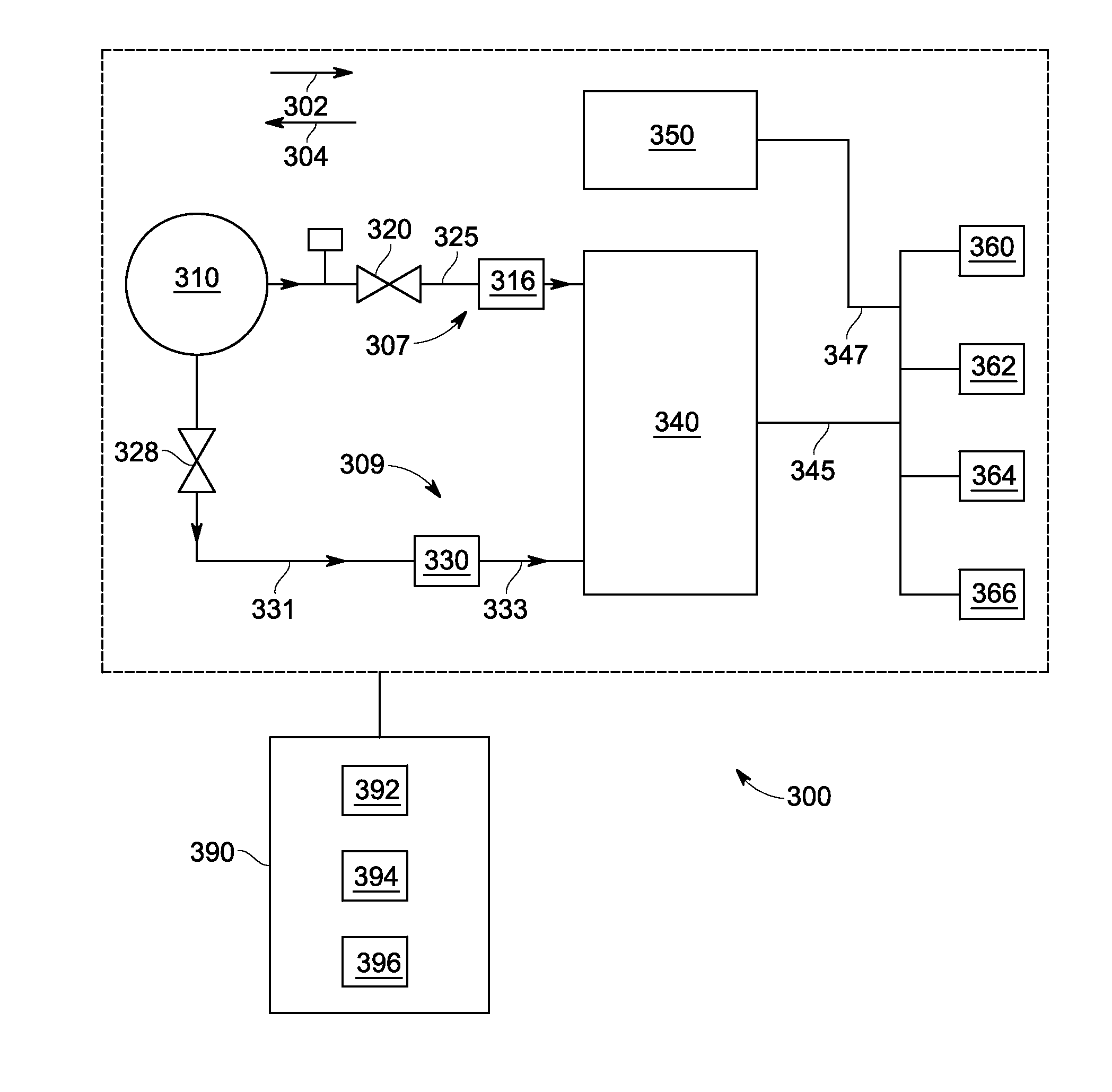
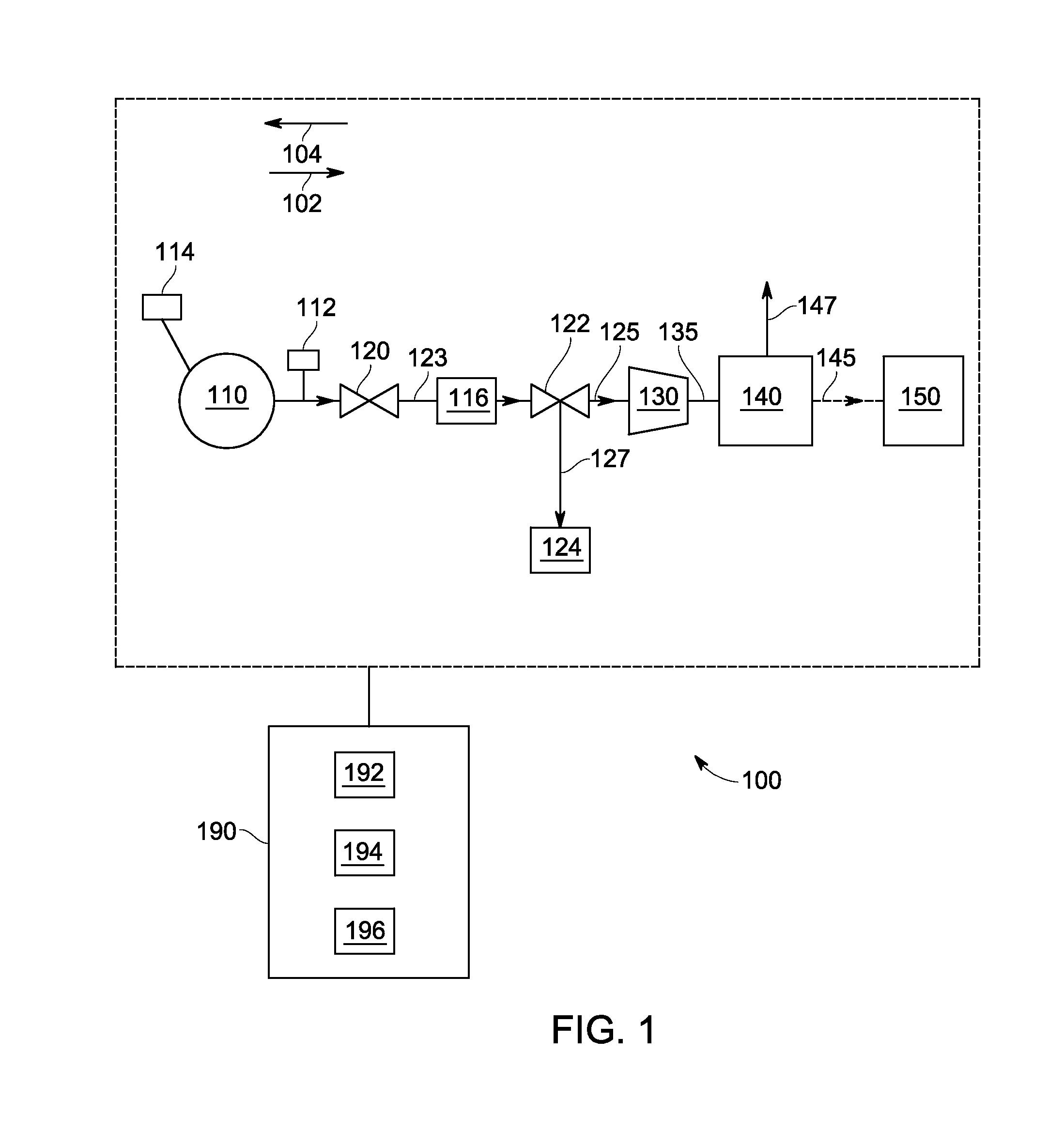
[0011]Various embodiments will be better understood when read in conjunction with the appended drawings. To the extent that the figures illustrate diagrams of the functional blocks of various embodiments, the functional blocks are not necessarily indicative of a division between hardware and / or circuitry. Thus, for example, one or more of the functional blocks may be implemented in a single piece of hardware or multiple pieces of hardware. Similarly, any programs may be stand-alone programs, may be incorporated as subroutines in an operating system, may be functions in an installed software package, and the like. It should be understood that the various embodiments are not limited to the arrangements and instrumentality shown in the drawings.

[0012]As used herein, the terms “system,”“unit,” or “module” may include a hardware and / or software system that operates to perform one or more functions. For example, a module, unit, or system may include a computer processor, controller, or ot...


PUM


Abstract

A system in one embodiment includes a detection unit, a boil-off auxiliary power unit, and a controller. The detection unit is configured to detect a characteristic of a boil-off gas stream from a cryotank configured to hold a cryogenic fluid. The boil-off auxiliary power unit is configured to receive the boil-off gas stream and use the boil-off gas stream to provide auxiliary power to a vehicle system. The controller is configured to acquire information from the detection unit corresponding to the characteristic; determine, using the information acquired from the detection unit, an available boil-off auxiliary energy that is available from the boil-off auxiliary power unit; determine a mode of operation of the vehicle system; determine a required auxiliary energy for the vehicle system; and to operate the auxiliary power unit based on the available boil-off auxiliary energy, the mode of operation, and the required auxiliary energy.

Description

BACKGROUND[0001]Cryogenic fluids may be used on-board aircraft, trains, ships, motor vehicles, or in other applications that limit the size or weight of a system utilizing cryogenic fluids. For example, some aircraft engines are configured to use natural gas as fuel. The natural gas may be stored on-board the aircraft as liquid natural gas (LNG), which is a cryogenic fluid. Cryogenic fluids may be stored on-board aircraft within a cryogenic tank that holds a volume of the cryogenic fluid. After a cryogenic tank is filled with LNG, the tank may be exposed to higher temperatures (e.g., higher temperatures than the boiling point of LNG). As ambient temperature increases, increasing amounts of LNG within the tank may evaporate as a boil-off gas, creating increasing pressure within the cryogenic tank. Thus, to address the increasing pressure within the cryogenic tank, the boil-off gas may be released from the tank, for example, through a valve. In some systems, the boil-off gas may be ve...

Claims


Application Information

Patent Timeline
Patent Type & Authority Applications(United States)
IPC IPC(8): F17C9/04F01K25/08F17C13/02
CPCB64D37/30B64D41/00F17C9/04F17C2221/033F17C2223/0161F17C2250/032F17C2265/031F17C2265/032F17C2265/066F17C2270/0105F17C2270/0168F17C2270/0173F17C2270/0189Y02T50/40B64D37/00F01K25/08F17C9/00F17C13/005F17C13/02F17C13/08F17C13/083
Inventor GERSTLER, WILLIAM DWIGHTHUDY, LAURA MICHELEKALRA, CHIRANJEEV
Owner GENERAL ELECTRIC CO
Why Eureka
Try Eureka