Intake passage structure for vehicle

Active Publication Date: 2014-06-26
HONDA MOTOR CO LTD
View PDF10 Cites 18 Cited by
  • Summary
  • Abstract
  • Description
  • Claims
  • Application Information

AI Technical Summary

Benefits of technology

[0021]Moreover, it is possible to increase the length of the upstream connecting tube inside the air cleaner and also to lengthen the connecting tube in accordance with the layout of the engine and the throttle body.
[0022]Moreover, it is possible to lengthen the upstream connecting tube and the downstream connecting tube in accordance with the layout of the engine and the throttle body.
[0023]Furthermore, the middle connecting tube makes it possible to connect the upstream connecting tube and the downstream connecting tube with a simple configuration.
[0024]Moreover, the engag

Problems solved by technology

However, in the case of the conventional intake passage structure described above, additional components such as bands are necessary for joint areas of each s

Method used


Image

  • Intake passage structure for vehicle
  • Intake passage structure for vehicle
  • Intake passage structure for vehicle

Examples


Example

[0037]Hereinbelow, an intake passage structure for a vehicle according to an embodiment of the present invention will be described with reference to the accompanying drawings. Note that directions such as front, rear, left, right, up, and down to be mentioned in the description should be considered to be identical to the directions based on the vehicle body unless otherwise noted. Moreover, reference numerals FR, UP, and LE shown in drawings denote the front side of the vehicle body, the upper side of the vehicle body, and the left side of the vehicle body, respectively.

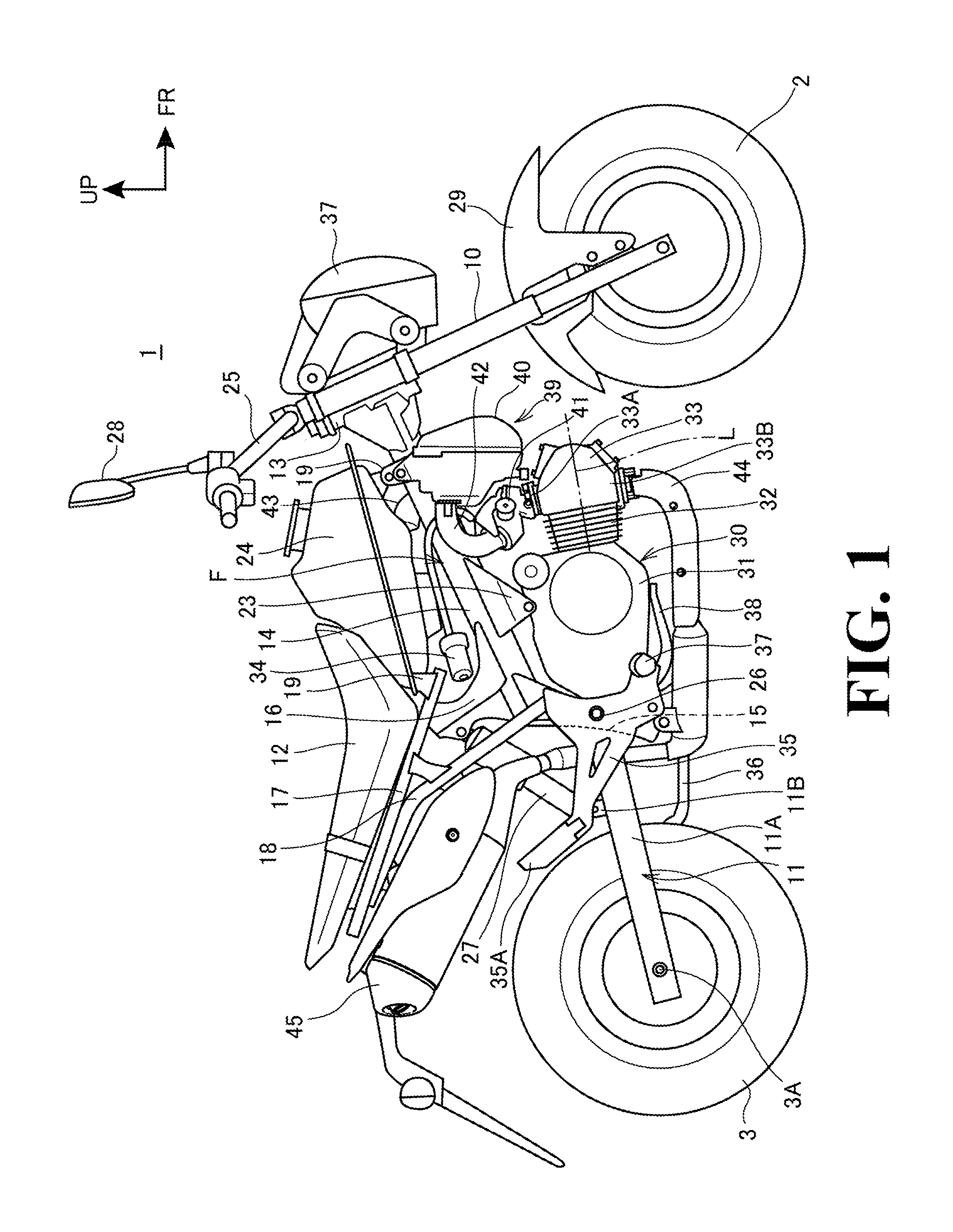
[0038]FIG. 1 is a right-side view of a motorcycle according to an embodiment of the present invention.

[0039]As shown in FIG. 1, a motorcycle 1 (vehicle) is a saddle-ride type vehicle in which: an engine 30 is disposed at the center of a vehicle body frame F in the front-rear direction; front forks 10 that support a front wheel 2 are steerably supported on the front end of the vehicle body frame F; a swingarm 11 that ...


PUM


Abstract

The length of a connecting tube in an intake passage structure for a vehicle can be secured, and the number of components around the connecting tube can be reduced. Provided is an intake passage structure for a vehicle including a connecting tube and an engine, the connecting tube connecting an air cleaner box which purifies air and a throttle body and formed of two or more separate components, the engine being configured to be supplied with purified air. In the intake passage structure, a joint area at which the connecting tubes are connected in a predetermined positional relation is disposed inside the air cleaner box.

Description

CROSS-REFERENCE TO RELATED APPLICATIONS[0001]The present application claims priority under 35 U.S.C. §119 to Japanese Patent Application No. 2012-083198, filed Mar. 30, 2012, the contents of which is incorporated herein, by reference, in its entirety.TECHNICAL FIELD[0002]The present invention relates to an intake passage structure for a vehicle including a connecting tube connecting an air cleaner and a throttle body.BACKGROUND OF THE INVENTION[0003]Heretofore, an intake passage structure for a motorcycle has been known in which a connecting tube for air to pass through to a throttle body after being purified by an air cleaner is formed of three separate components outside the air cleaner (see Japanese Patent Application Publication No. 2008-248718, for example). Specifically, of the three components, the upstream and downstream tubes are made of rubber, and the middle tube connecting them to each other and having multiple bent portions is formed by blow molding. In this configurati...

Claims


Application Information

Patent Timeline
IPC IPC(8): F02M35/10F02M35/16
CPCF02M35/162F02M35/10085F02M35/0202F02M35/024F02M35/10039
Inventor SHIMOMURA, NOBUYUKIOKAMOTO, TOMOYUKIOMIKA, YASUSHI
Owner HONDA MOTOR CO LTD
Why Eureka
Try Eureka