Phase locked loop system and working method thereof

a phase lock and loop technology, applied in the direction of electrical equipment, pulse automatic control, etc., can solve the problems of difficult to determine the loop bandwidth for both and the inability to restrain the noise of the fin and the vco at the same time, so as to reduce the output. , the effect of limiting the noise of the inpu

Inactive Publication Date: 2014-06-26
IPGOAL MICROELECTRONICS (SICHUAN) CO LTD
View PDF10 Cites 4 Cited by
  • Summary
  • Abstract
  • Description
  • Claims
  • Application Information

AI Technical Summary

Benefits of technology

[0012]An object of the present invention is to provide a PLL system and a working method thereof for restraining input noise as well as VOC noise.

Problems solved by technology

The problem of the conventional PLL system is that the noise of the Fin and the VCO cannot be restrained at the same time.
Obviously, the loop bandwidth is difficult to be determined for both the Fin and the VCO.

Method used


Image

  • Phase locked loop system and working method thereof
  • Phase locked loop system and working method thereof
  • Phase locked loop system and working method thereof

Examples


Embodiment Construction

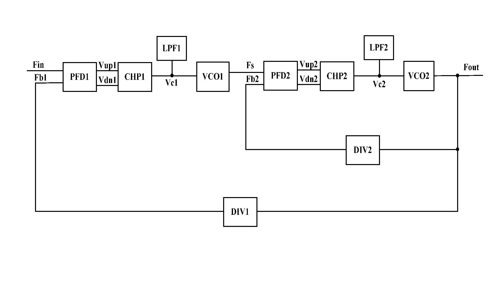
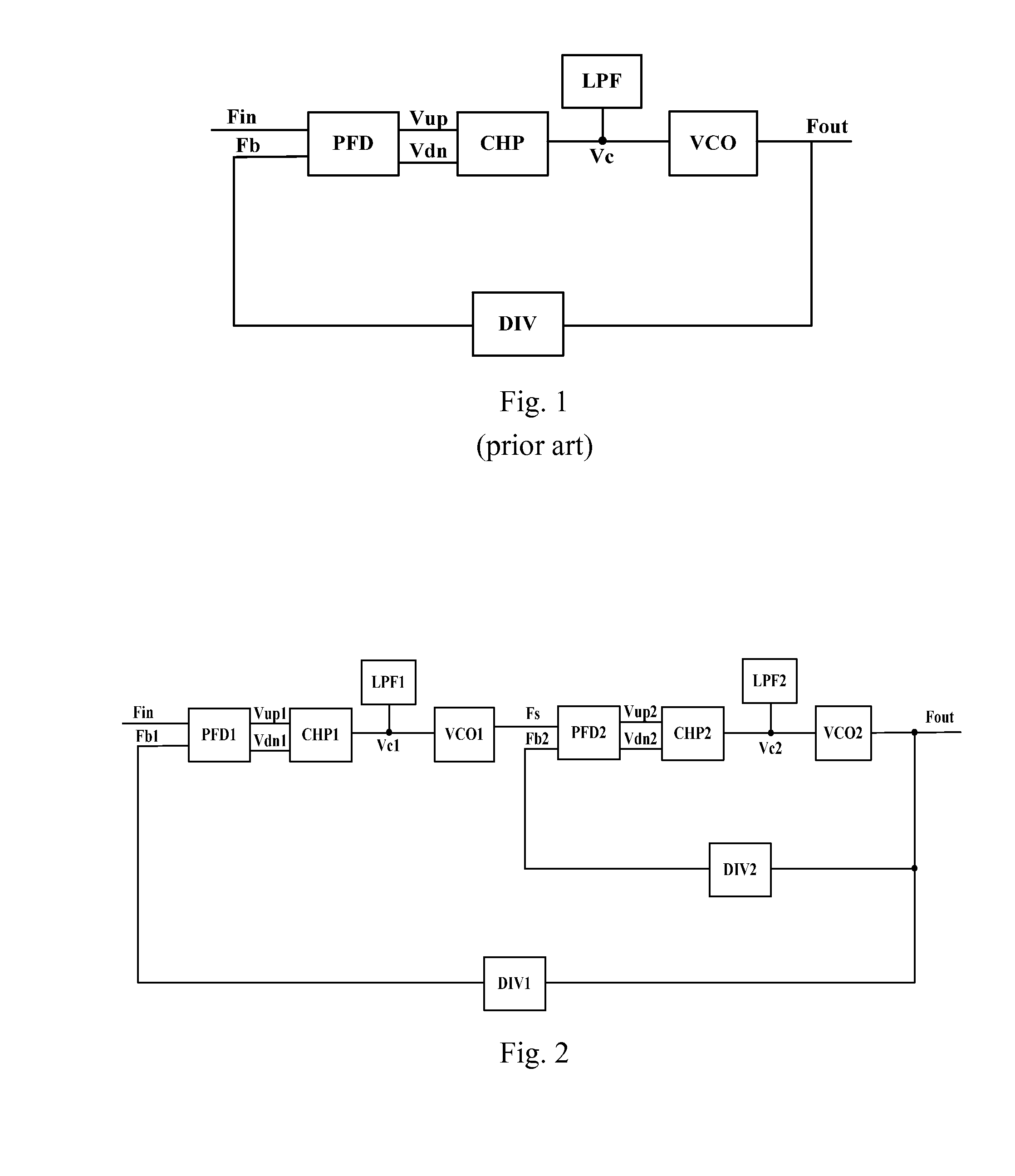
[0045]Referring to FIG. 2 of the drawings, a PLL system according to a preferred embodiment of the present invention is illustrated, comprising:

[0046]an input end;

[0047]a first PFD1 connected to the input end;

[0048]a first CHP1 connected to the first PFD1;

[0049]a first LPF1 connected to the first CHP1;

[0050]a first VCO1 connected to the first CHP1 and the first LPF1;

[0051]a second PFD2 connected to the first VCO1;

[0052]a second CHP2 connected to the second PFD2;

[0053]a second LPF2 connected to the second CHP2;

[0054]a second VCO2 connected to the second CHP2 and the second LPF2;

[0055]an output end connected to the second VCO2;

[0056]a first DIV1 connected to the first PFD1, the second VCO2 and the output end; and

[0057]a second DIV2 connected to the second PFD2, the second VCO2 and the output end;

[0058]wherein the second PFD2, the second CHP2, the second LPF2, the second VCO2 and the second DIV2 form an inner loop; and the inner loop, the first PFD1, the first CHP1, the first LPF1, the...


PUM


Abstract

A PLL system includes: an input end; an output end; a first PFD; a first CHP connected to the first PFD; a first LPF connected to the first CHP; a first VCO connected to the first CHP and the first LPF; a second PFD connected to the first VCO; a second CHP connected to the second PFD; a second LPF connected to the second CHP; a second VCO connected to the second CHP and the second LPF; a first DIV connected to the first PFD and the second VCO; and a second DIV connected to the second PFD and the second VCO. A working method of the PLL system is also provided, which can restrain input noise as well as phase noise of the second VOC in such a manner that noise of the PLL system is well restrained.

Description

BACKGROUND OF THE PRESENT INVENTION[0001]1. Field of Invention[0002]The present invention relates to a phase locked loop (PLL) system, and more particularly to a PLL system which can restrain noise of a PLL and a working method thereof.[0003]2. Description of Related Arts[0004]Referring to FIG. 1 of the drawings, a structural view of a PLL system according to a prior art is illustrated, wherein the PLL comprises:[0005]a phase frequency detector (PFD);[0006]a charge bump (CHP);[0007]a low-pass filter (LPF);[0008]a voltage-controlled oscillator (VCO); and[0009]a digital frequency divider (DIV);[0010]wherein the PFD detects a phase difference between an input clock Fin and a feedback clock Fb, and generates a CHP control signals Vup and Vdn for controlling the CHP; the CHP charges or discharges a voltage end Vc under control of the Vup and the Vdn; the LPF filters out high dither of the Vc; the VCO generates an output clock Fout under control of the Vc; usually, the Fout is linear with...

Claims


Application Information

Patent Timeline
Patent Type & Authority Applications(United States)
IPC IPC(8): H03L7/07
CPCH03L7/235
Inventor FAN, FANGPING
Owner IPGOAL MICROELECTRONICS (SICHUAN) CO LTD
Why Eureka
Try Eureka