Lens driving apparatus, camera module, and camera-equipped mobile terminal

Active Publication Date: 2014-06-26
MITSUMI ELECTRIC CO LTD
View PDF3 Cites 147 Cited by
  • Summary
  • Abstract
  • Description
  • Claims
  • Application Information

AI Technical Summary

Benefits of technology

[0014]An object of the present invention is to provide a lens driving apparatus, a camera module, and a ca

Problems solved by technology

However, it is difficult to achieve further size reduction with the configuration of the conventional lens driving apparatuses.
In addition, the external siz

Method used


Image

  • Lens driving apparatus, camera module, and camera-equipped mobile terminal
  • Lens driving apparatus, camera module, and camera-equipped mobile terminal
  • Lens driving apparatus, camera module, and camera-equipped mobile terminal

Examples


Embodiment Construction

[0028]Now, an embodiment of the present invention will be described with reference to the accompanying drawings.

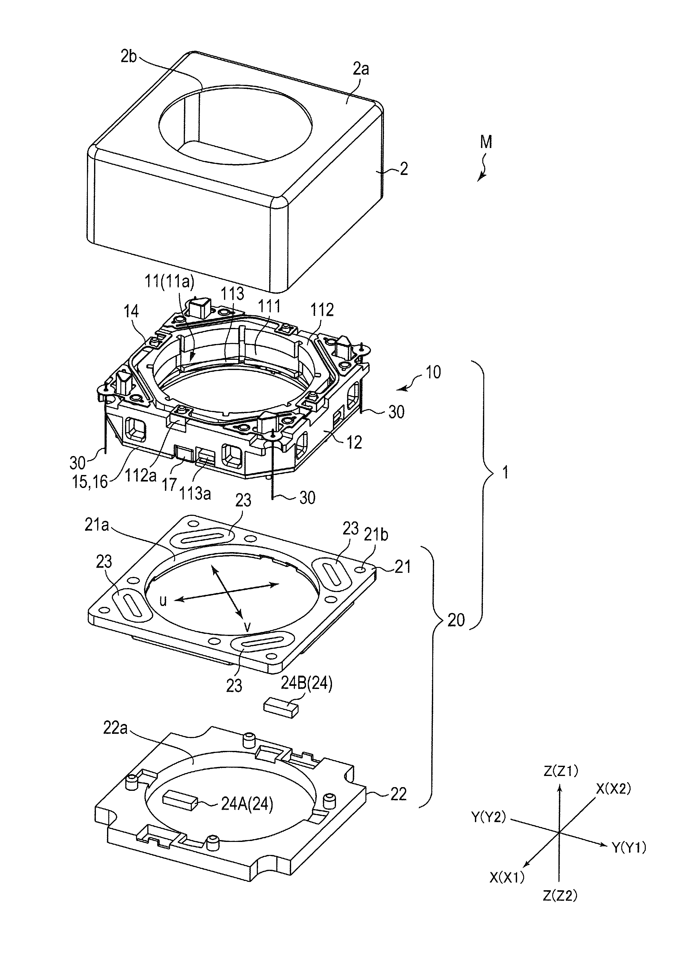
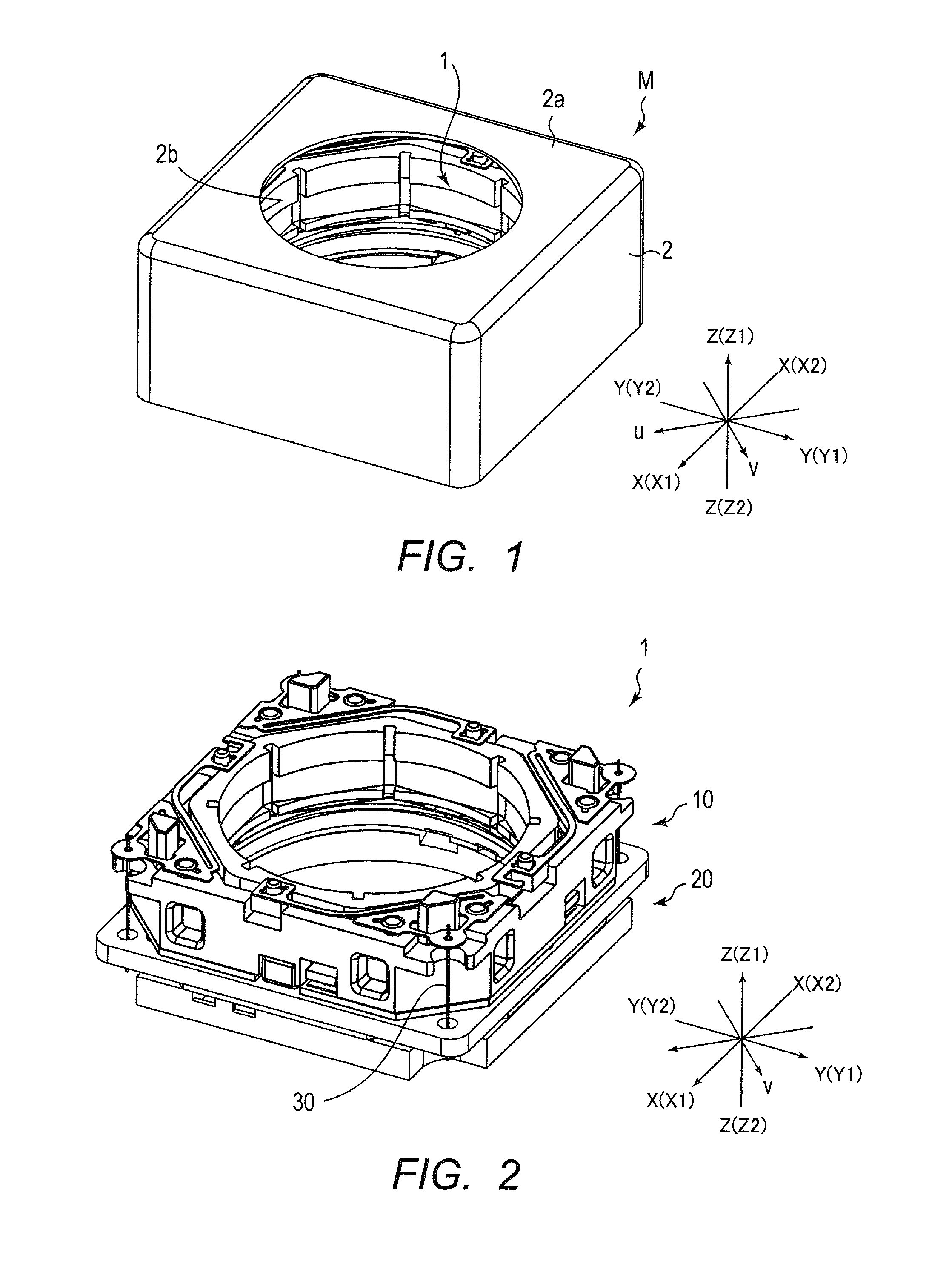
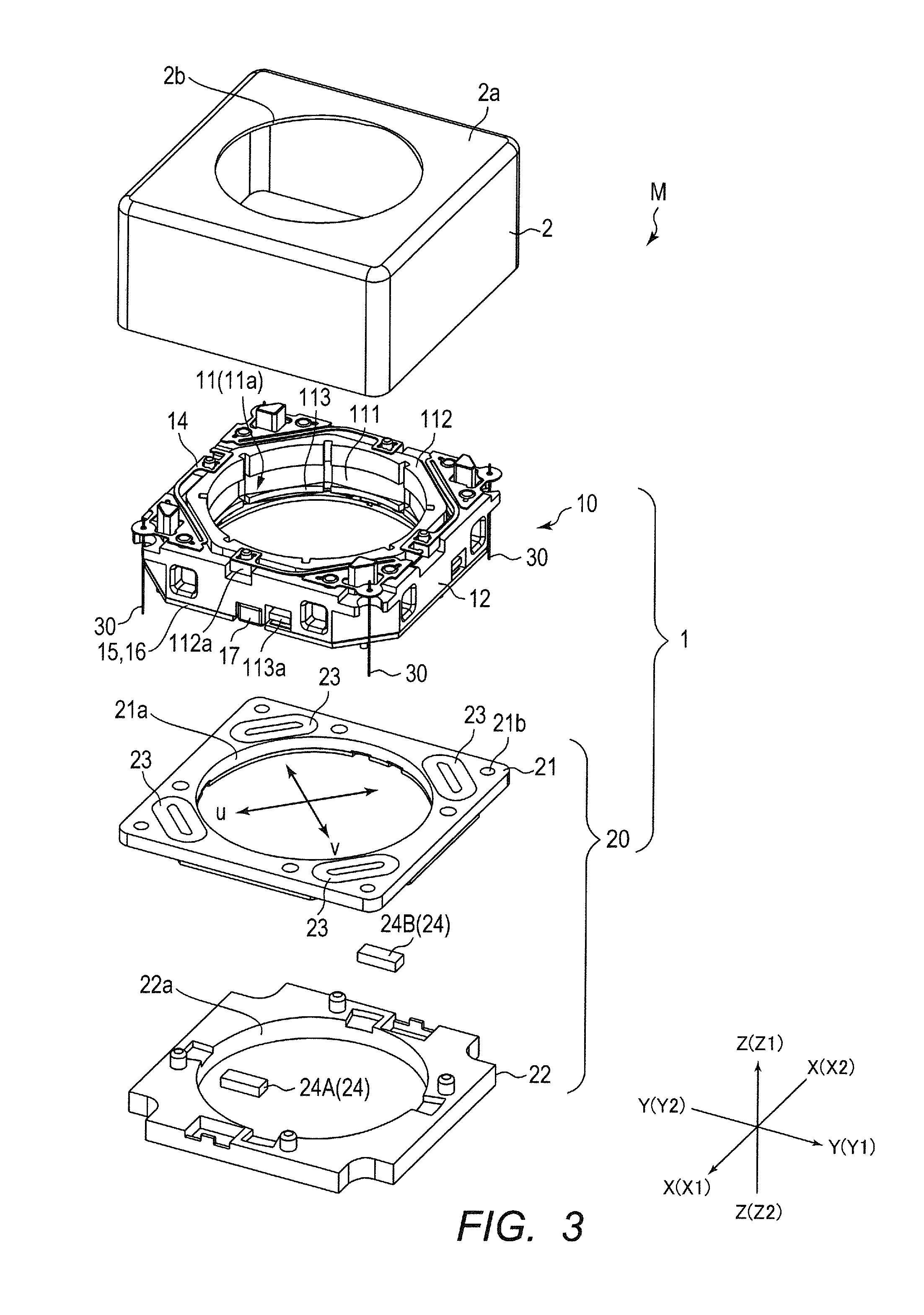
[0029]FIG. 1 is a perspective view illustrating an external appearance of camera module M according to an embodiment of the present invention. FIG. 2 is a perspective view illustrating an external appearance of lens driving apparatus 1 to be covered by shield cover 2. FIG. 3 is an exploded perspective view illustrating camera module M. FIG. 4 is an exploded perspective view illustrating movable section 10 of lens driving apparatus 1.

[0030]For the description, orthogonal coordinate system (X, Y, and Z) is used, as illustrated in FIG. 1 to FIG. 3. In FIG. 1 to FIG. 3, the X direction is the front-rear direction (depth direction), the Y direction is the horizontal direction (width direction), and the Z direction is the vertical direction (height direction).

[0031]In FIG. 1 to FIG. 3, the Z direction is the optical axis direction of a lens. In addition, the intermediate directi...


PUM


Abstract

A lens driving apparatus includes: a lens holder having an auto-focusing first coil; a lens holder moving section that supports the lens holder in such a manner that the lens holder is movable in a first direction; a driving magnet disposed at four corners of the lens holder moving section and moves the lens holder in the first direction in cooperation with the first coil; a camera-shake correction second coil that moves the lens holder in a second direction and a third direction in cooperation with the driving magnet, the second direction and the third direction corresponding to diagonal directions of the lens holder moving section; and a supporting section that supports the lens holder moving section in such a manner that the lens holder moving section is movable in the second direction and the third direction.

Description

CROSS REFERENCE TO RELATED APPLICATIONS[0001]This application is entitled to and claims the benefit of Japanese Patent Application No.2012-282762, filed on Dec. 26, 2012, the disclosure of which including the specification, drawings and abstract is incorporated herein by reference in its entirety.BACKGROUND OF THE INVENTION[0002]1. Field of the Invention[0003]The present invention relates to a lens driving apparatus for use in a camera equipped with an auto-focusing function and a camera-shake correction function, a camera module, and a camera-equipped mobile terminal.[0004]2. Description of Related Art[0005]Conventionally, as a camera installed in a mobile terminal such as a smartphone, a camera equipped with an auto-focusing function and a camera-shake correction function is known. Such a camera adopts a lens driving apparatus that automatically focuses on a subject to be captured by moving a lens barrel and can reduce an image defect by correcting a camera-shake (vibration) when ...

Claims


Application Information

Patent Timeline
IPC IPC(8): G02B7/09G02B27/64
CPCG02B7/08H04N23/55G02B27/64G02B27/646G03B17/02G02B7/09G02B7/02H04N23/00H04N23/40H04N23/687G02B7/025G02B7/04
Inventor HAYASHI, ICHIROENTA, YOHEI
Owner MITSUMI ELECTRIC CO LTD
Why Eureka
Try Eureka