Method of powering mobile equipment

Active Publication Date: 2014-06-26
FLSMIDTH AS
View PDF3 Cites 2 Cited by
  • Summary
  • Abstract
  • Description
  • Claims
  • Application Information

AI Technical Summary

Benefits of technology

[0009]The present invention provides a method of supplying operating electrical power from a stationary power source to a mobile conveyor utilized in material handling at a mine site as the conveyor moves over a predetermined path at

Problems solved by technology

It is impractical for mobile trippers to carry the entire amount of power cable needed to travel over such distances, as the size of cable reel required can become impractically large for very long cables.
Although a cable drum can hold significantly more cable than a cable reel, its use adds substantially more length and cost to the tripper conveyor compared to a cable reel.
In addition, weight is an issue for trippers, which can weigh 200,000 pounds or more.
If the t

Method used


Image

  • Method of powering mobile equipment
  • Method of powering mobile equipment
  • Method of powering mobile equipment

Examples


Embodiment Construction

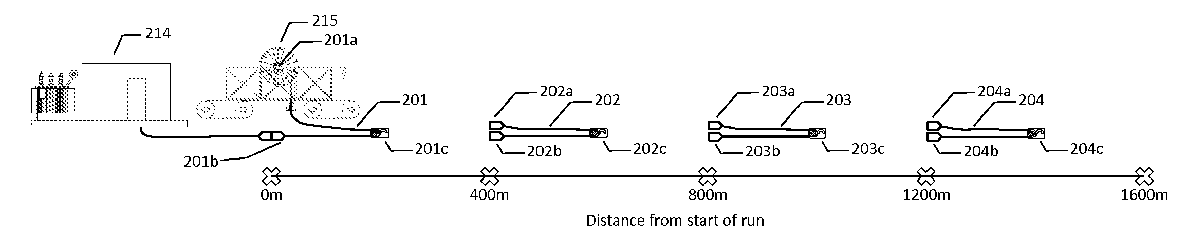
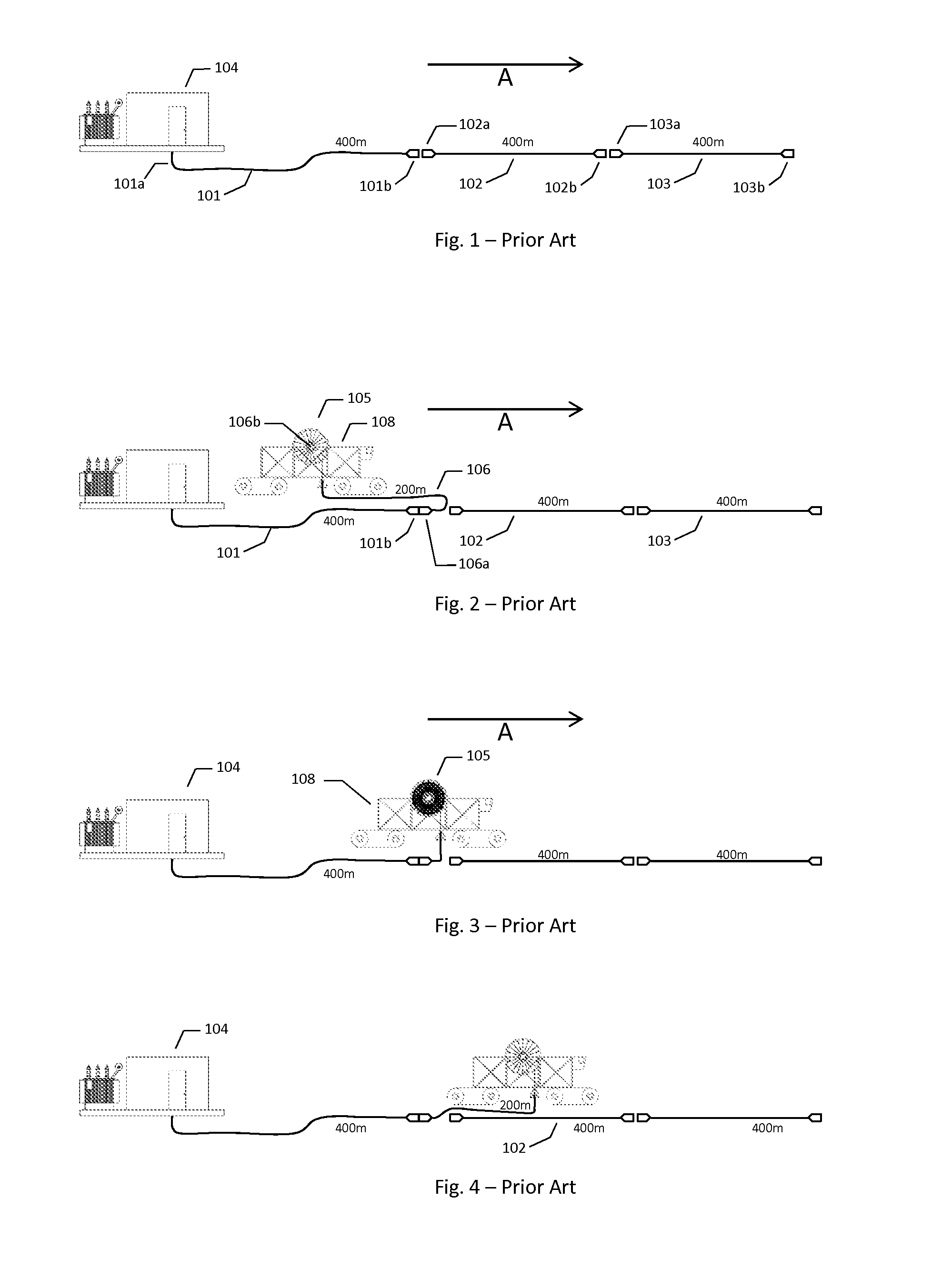
[0021]FIG. 1 depicts a prior art layout of cables prior to the movement of the mobile conveyor. Individual cables 101, 102 and 103, each 400m in length, are laid out in combination parallel to the path that the conveyor will move, which is in the direction of arrow A. Cable 101 has on one end 101a, which in the depicted view is the left end, an electrical connector or plug (not shown) that is wired into the electric house 104 which provides electrical power to the cable. On cable 101's other, i.e. right, end there is electrical plug 101b. Cables 102 and 103 each have an electrical plug, respectively 102a and 103a on each cable's left end that is located closer to electric house 104 and a plug, respectively 102b and 103b, on each cable's opposite, i.e. right, end that is located further from electric house 104.

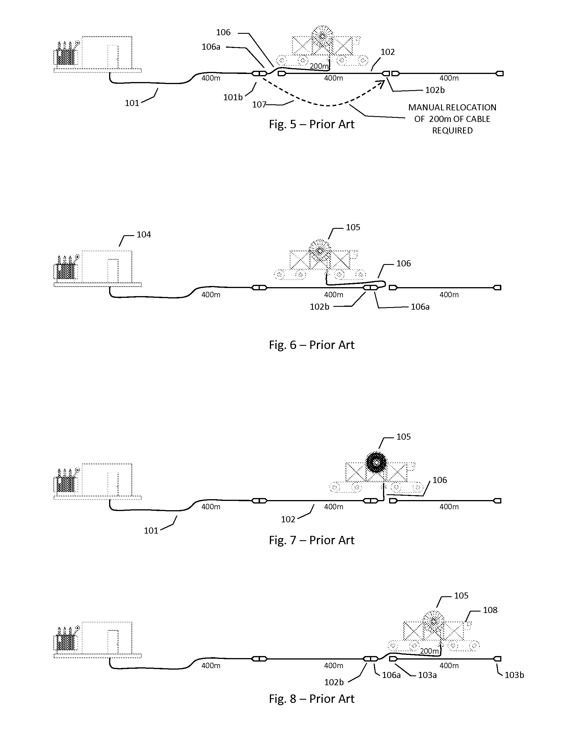
[0022]FIG. 2 is the first in a sequence showing the procedure, according to one prior art method, for powering a mobile conveyor as it traverses a path in a mining environment ...


PUM

PropertyMeasurementUnit
Poweraaaaaaaaaa

Abstract

A method of providing operating electrical power from a stationary power source to a mobile conveyor utilized in material handling at a mine site as the conveyor moves over a predetermined path at the site without having to move long lengths of cable as the conveyor moves away from the power source. The method utilizes a cable reel that features a power receptacle into which a cable connector can be easily plugged and unplugged.

Description

CROSS-REFERENCE TO RELATED APPLICATION[0001]This application claims the benefit of U.S. Provisional Application No. 61 / 580,748, filed Dec. 28, 2011.FIELD OF INVENTION[0002]The present invention relates to material handling and, more particularly, relates to apparatuses and methods for stacking material such as ores, minerals or agglomerated material at mine sites. In more particularity, this invention relates to a method of powering large mobile equipment such as very large and slow moving equipment used in such applications.[0003]BACKGROUND AND DESCRIPTION OF THE PRIOR ART[0004]Conveyors may be used in stackers to stack material or in devices configured to reclaim material from a stack. Typically, systems designed for stacking and reclaiming material utilize a number of conveyors. One set of conveyors is typically used to convey material to a stacker for stacking in a particular area. Another set of conveyors is used to reclaim the material stacked in that area. Examples of systems...

Claims


Application Information

Patent Timeline
IPC IPC(8): H02G11/02H02G1/06
CPCH02G11/02H02G1/06Y10T29/49174
Inventor CROWE, JAMES
Owner FLSMIDTH AS
Why Eureka
Try Eureka