
Quality of service support using stacked memory device with logic die

a technology of logic die and memory device, which is applied in the field of die-stacked memory device, can solve the problems of affecting the processing efficiency unnecessarily complicating the design of the processing system,

Active Publication Date: 2014-06-26
ADVANCED MICRO DEVICES INC
View PDF4 Cites 36 Cited by
  • Summary
  • Abstract
  • Description
  • Claims
  • Application Information

AI Technical Summary

Benefits of technology

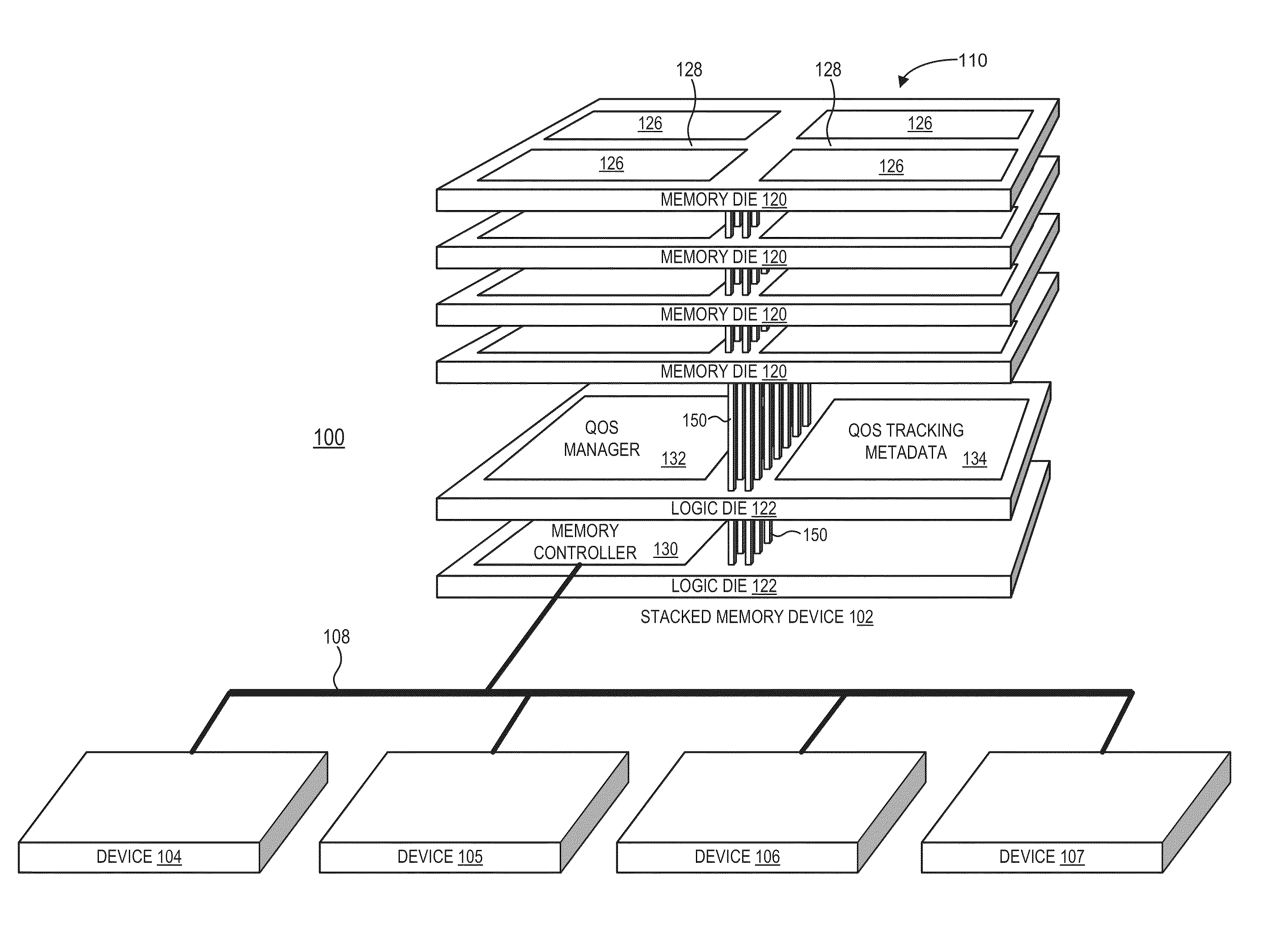
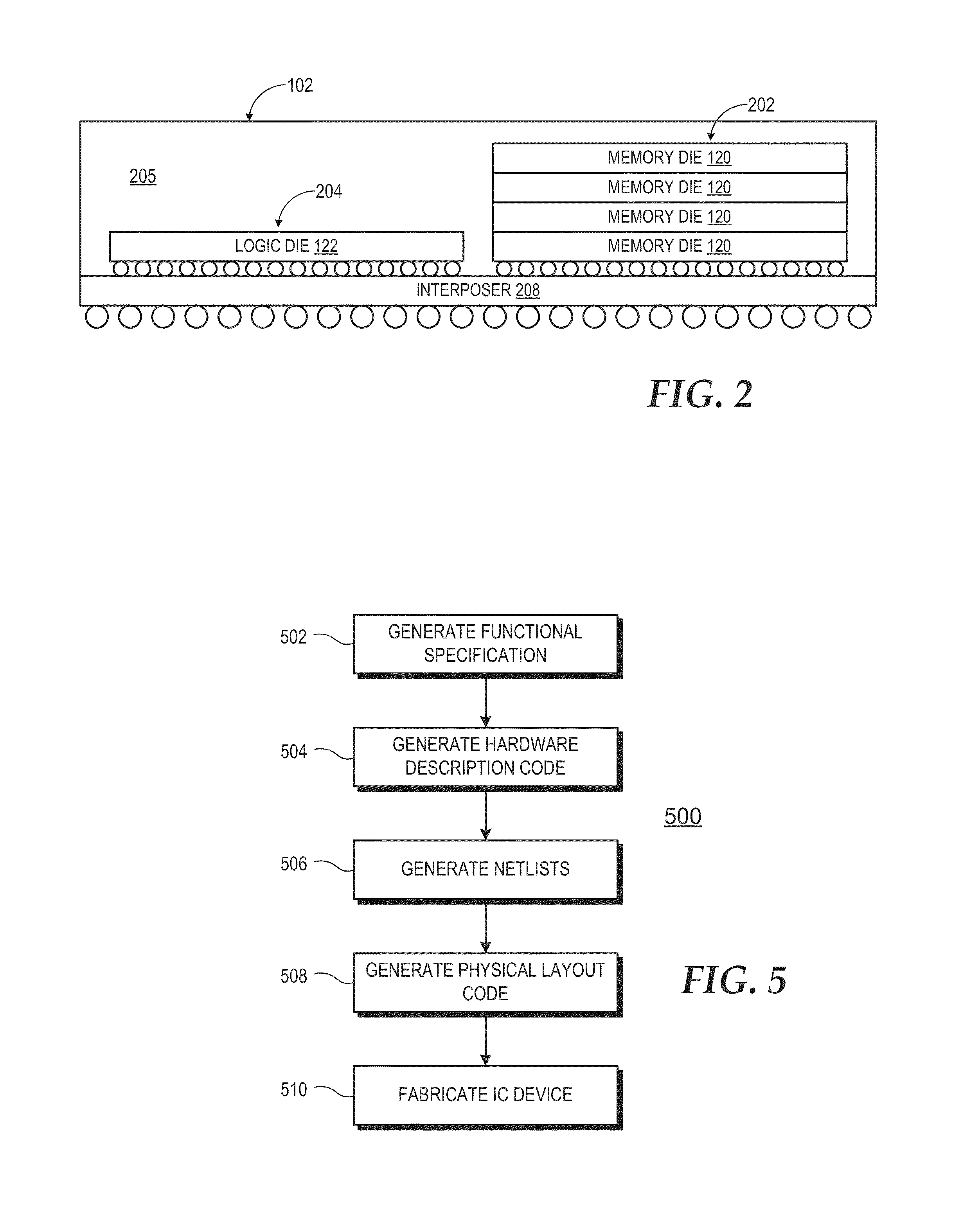
The present disclosure relates to processing systems and, more particularly, to improving processing efficiency and decreasing power consumption in processing systems that use a die-stacked memory device with a logic die implementing a hardware quality of service (QoS) manager. The QoS manager provides centralized QoS functionality in furtherance of one or more specified QoS objectives, such as ensuring efficient use of system memory bandwidth and reducing latency and power consumption. The QoS manager monitors memory access operations performed by a memory controller and updates QoS tracking metadata accordingly. The patent text also describes a method for designing and fabricating an integrated circuit (IC) device implementing a die-Stacked memory device.

Problems solved by technology

The system memory typically is shared among the devices, and thus processing efficiency of the processing system may be impacted by excessively low memory bandwidth or excessively high memory access latency during times of high collective utilization of the system memory by the devices.
Conventional techniques to provide certain quality of service (QoS) levels for memory accesses at the system level typically rely on some form of coordination among the devices sharing the system memory, which can unnecessarily complicate the design of the processing system.

Method used


Image

  • Quality of service support using stacked memory device with logic die
  • Quality of service support using stacked memory device with logic die
  • Quality of service support using stacked memory device with logic die

Examples


Embodiment Construction

[0011]FIGS. 1-5 illustrate example techniques for improved processing efficiency and decreased power consumption in a processing system through the use of a die-stacked memory device implementing an integrated QoS manager to provide centralized QoS functionality in furtherance of one or more specified QoS objectives for the sharing of the memory resources by components (referred to herein as “sharers”) of the processing system. The die-stacked memory device includes a set of one or more stacked memory dies and a set of one or more logic dies. The one or more logic dies implement hardware logic for a memory controller and the QoS manager. The memory controller is coupled to the memory cell circuitry and is coupleable to one or more devices external to the set of one or more stacked memory dies and set of logic dies via one or more corresponding interfaces. The memory controller operates to service memory access requests from the one or more external devices. The QoS manager comprises...


PUM


Abstract

A die-stacked memory device implements an integrated QoS manager to provide centralized QoS functionality in furtherance of one or more specified QoS objectives for the sharing of the memory resources by other components of the processing system. The die-stacked memory device includes a set of one or more stacked memory dies and one or more logic dies. The logic dies implement hardware logic for a memory controller and the QoS manager. The memory controller is coupleable to one or more devices external to the set of one or more stacked memory dies and operates to service memory access requests from the one or more external devices. The QoS manager comprises logic to perform operations in furtherance of one or more QoS objectives, which may be specified by a user, by an operating system, hypervisor, job management software, or other application being executed, or specified via hardcoded logic or firmware.

Description

BACKGROUND[0001]1. Field of the Disclosure[0002]The present disclosure generally relates to processing systems and, more particularly, to die-stacked memory devices.[0003]2. Description of the Related Art[0004]Processing systems generally implement system memory separately from the devices implementing processors, input / output (I / O) components, and other components. The system memory typically is shared among the devices, and thus processing efficiency of the processing system may be impacted by excessively low memory bandwidth or excessively high memory access latency during times of high collective utilization of the system memory by the devices. Conventional techniques to provide certain quality of service (QoS) levels for memory accesses at the system level typically rely on some form of coordination among the devices sharing the system memory, which can unnecessarily complicate the design of the processing system.BRIEF DESCRIPTION OF THE DRAWINGS[0005]The present disclosure may...

Claims


Application Information

Patent Timeline
Patent Type & Authority Applications(United States)
IPC IPC(8): G06F12/00
CPCG06F13/16H01L2924/15311H01L2924/1434H01L2924/1431H01L2224/16227G06F12/00G06F12/0246
Inventor HSU, LISA R.LOH, GABRIEL H.BECKMANN, BRADFORD M.IGNATOWSKI, MICHAEL
Owner ADVANCED MICRO DEVICES INC
Learn More