Since the cushion acts like an insulator, the heat is deflected back up to the body creating a rise in
skin temperature.
Moisture softens the
skin and makes it more susceptible to physical damage.
This technique is very good, but the process can be
time consuming and very expensive and is prone to fitment problems if the user grows or changes shape by gaining or losing weight.
The reason that this type of foam has not been used for
wheelchair cushions is that it is not very resilient.
Unlike
polyurethane foams that are designed to have a lot of elasticity, the foams in cushions of current embodiments only allow a very small amount of immersion.
The lack of resiliency would not matter much if the present foam was used to produce cushions that are molded to the exact shape of the user, but the lack of
compressibility does not work well with a more generic cushion configuration that requires a lot of immersion.
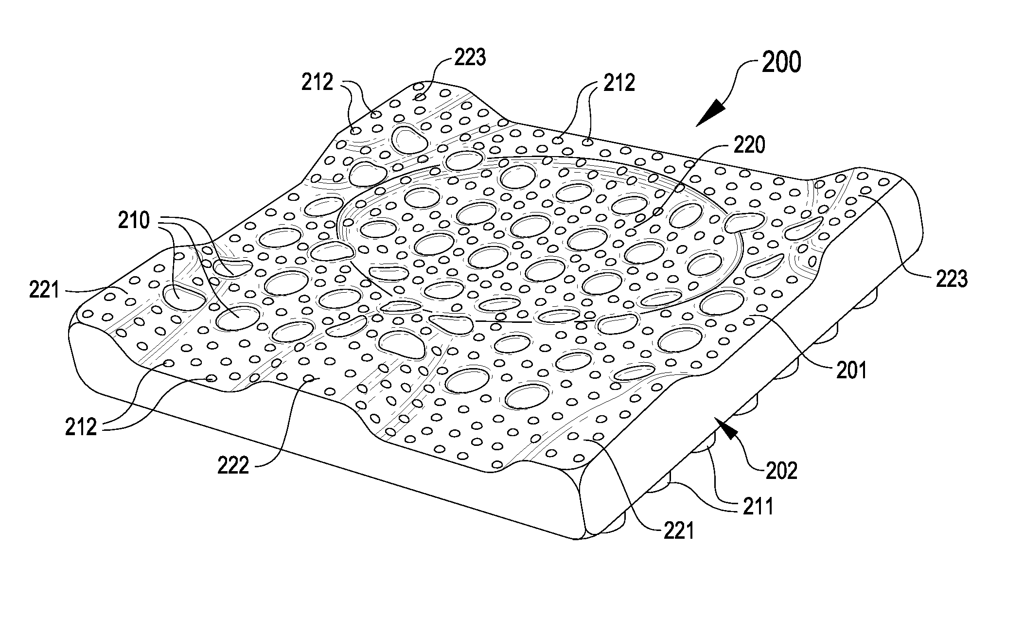
Whereas pre-contoured top surfaces of other commercial wheelchair cushions may rely on both their pre-contour and
compressibility to achieve their pressure distribution, such cushions are not using pre-
contouring, compression, and bending to achieve a dynamic redistribution of pressure away from the areas of
high pressure to areas of lower pressure as in current embodiments which incorporate a pre-contoured top surface not unlike other commercial wheelchair cushions.
Because the substantial
compressibility of other foam cushions responds to load by compressing to allow immersion, such cushions do not
resist pelvic retrusion due to slouching.
The accompanying process of modeling a person's foot and custom-fabricating a corresponding prescription orthotic is often expensive and time-consuming, but such individually customized prescription
orthotics are generally considered as providing the best results in the art.
In addition, existing orthopedic
orthotics suffer other drawbacks.
This
perspiration may become absorbed in the orthotic or shoe, causing undesirable and irremovable odors which result in a shortened useable lifespan of the orthotic or shoe.
Moisture and heat may also lead to diminished
skin integrity, resulting in sores and the like.
Although some
orthotics are equipped with holes in an effort to allow
airflow to ameliorate these conditions, the ventilation achieved is generally inadequate.
Further drawbacks can include limited useable lifespan and high expense resulting from the materials used in either prescription or generic orthotics.
While this is an effective precautionary measure that prevents the need to constantly replace mattresses, this practice does have drawbacks.
In addition to preventing the passage of
moisture, the plastic often also prevents effective dissipation of heat, reflecting the heat back toward the patient instead of allowing the heat to pass into the mattress.
Even mattress overlays which are not water-proof and which are used primarily for improved support or comfort can also present heat buildup issues, as the
overlay often acts as a further insulating layer that may slow heat dissipation.
However, several problems may occur with items placed in a pet
crate.
First, many animals have a tendency to chew on or eat items left in their immediate vicinity.
Furthermore, frequently pets may defecate or urinate in the
crate if left in the
crate too long or if otherwise stressed or uncomfortable or unaccustomed to the crate.
When this occurs, often the pet waste will ruin items in the crate, requiring unpleasant or difficult cleanup and costly replacement of the item.
However, current yoga mats have a number of drawbacks, most notably ventilation.
Sweat can thus accumulate on the mat, making the mat not only unpleasantly slimy, but also potentially dangerously slippery
In addition, since many helmets fit very closely to the head, resulting heat buildup and ventilation issues frequently arise.
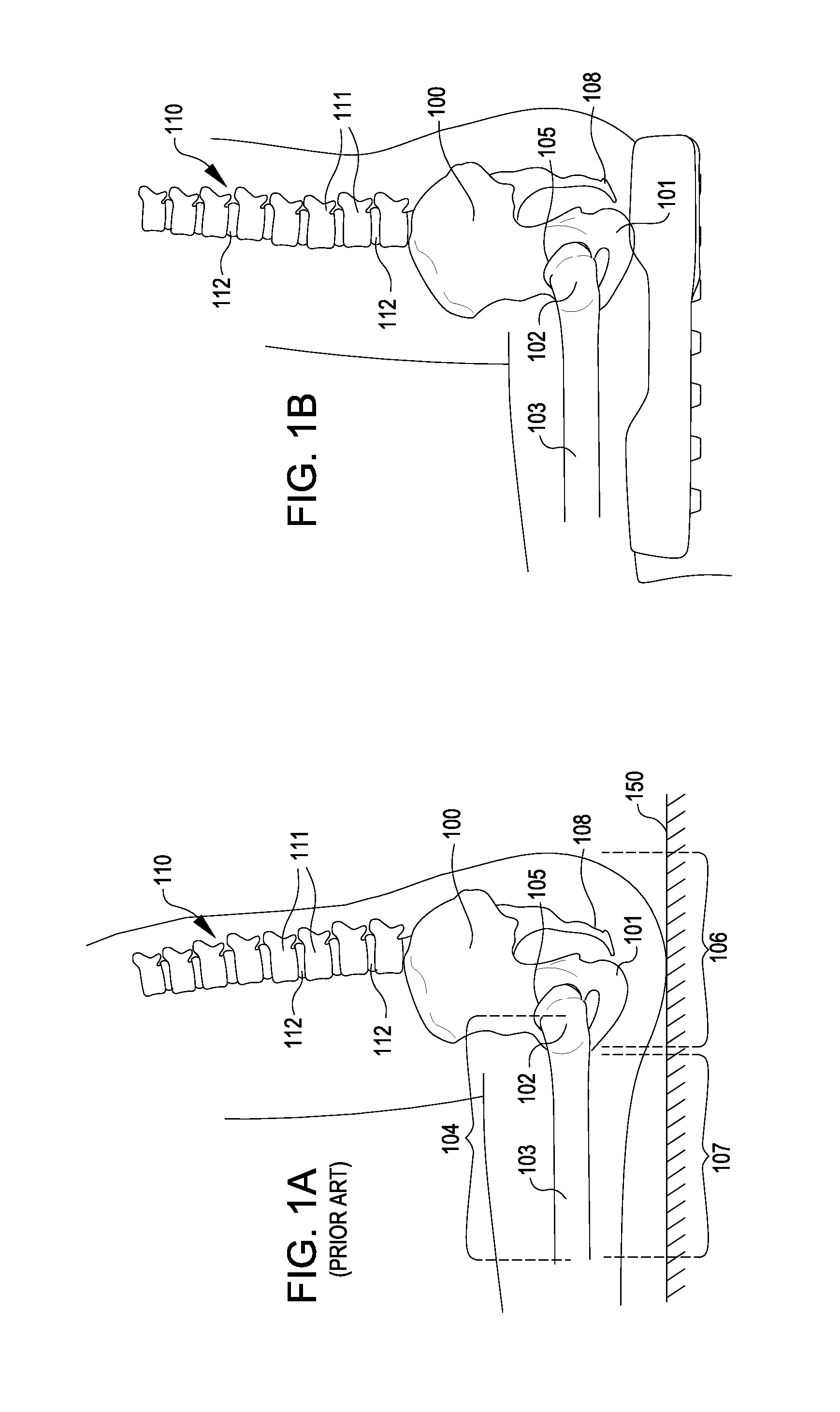
Several general anatomical areas can be problematic for patients that develop presure sores and the health care professionals and hospitals that work with them.
The boots are cumbersome,
time consuming to put on and take off, and often make walking difficult or impossible when worn by a patient.
For example, an increase of 6° (a common amount in a boot) could raise the requirement for
oxygen and other life sustaining nutrients by 60%, dramatically increasing the rate of
tissue damage and concurrent sore development.
When using a device that only supports the back of the leg, gravity and the weight of any
bed covers tend to pull the
entire foot and leg into lateral rotation.
Rotating both legs and feet in this fashion is not usually tolerated by patients, so care providers often resort to the addition of pillows and / or pads stacked to the side of the foot to help prevent this movement.
However, additional padding can act as further insulators and cause further heat build-up, thereby negating any ventilation benefit from suspending the foot in the air.
Pressure on the foot (i.e., from gravity and any
bed covers) can also cause the foot to move downward into
plantar flexion.
As most people do not have the ability or
range of motion to have their foot in this “on point” posture, having the foot forced into planter flexion is also uncomfortable for most people.
As a result, extra padding is often added to alleviate the flexion, thereby further impeding ventilation.

