Elevator

a technology of a roping device and a roping rod, which is applied in the direction of elevators, building lifts, transportation and packaging, etc., can solve the problems of affecting the safety of passengers, causing sudden jerks, and causing damage to the inside of the car, so as to facilitate a small bending radius without losing cross-sectional area, and good longitudinal force transmission ability of the roping

Active Publication Date: 2014-07-03
KONE CORP
View PDF16 Cites 18 Cited by
  • Summary
  • Abstract
  • Description
  • Claims
  • Application Information

AI Technical Summary

Benefits of technology

[0006]It is brought forward a new elevator. In a preferred embodiment of the invention, the elevator comprises an elevator car and a counterweight, and a first roping between the elevator car and counterweight suspending the elevator car and the counterweight, the first roping comprising at least one rope. The elevator further comprises a second roping between the elevator car and counterweight suspended to hang from the elevator car and counterweight, the second roping comprising at least one rope, and a rope wheel arrangement, having at least one rope wheel around which said at least one rope of the second roping passes. The longitudinal force transmission capability of said at least one rope of the second roping is based essentially on non-metallic fibers, and in that said at least one rope of the second roping is a belt-like rope having at least one contoured side provided with guide rib(s) and / or guide groove(s) oriented in the longitudinal direction of the rope, said side being fitted to pass against a contoured circumference of a rope wheel of said rope wheel arrangement, said circumference being provided with guide rib(s) and / or guide groove(s) so that said contoured circumference forms a counterpart for said contoured side of the rope. The sensitivity of the rope for disturbances caused by its lightness and the belt-like form are compensated for by the lateral guidance, which guidance is achieved by the rib-groove shapes of the rope and the circumference forming counterparts for each other. This configuration brings the benefit of a light-weighted roping between the elevator car and the counterweight without disturbances causing unintended lateral movement for the roping. The rope(s) being belt-like facilitates a small bending radius without losing cross-sectional area. Thus, the longitudinal force transmission capabilities of the roping are good.

Problems solved by technology

These types of incidents would be harmful and dangerous, because they might cause displacement of the suspension ropes.
Sudden jerks might also be caused for the people inside the car.
Metallic ropes have the drawback that they are heavy, which causes several challenges, for instance in energy consumption and dimensioning.
It has been found out that if the ropes of the second roping are light-weighted and belt-like they may occasionally take strong disturbance from air flows occurring in the hoistway.
Especially elevators with long lifting height, and therefore with long free rope spans, are detected to be prone to this problem.
The disturbance may cause unintended horizontal movement (e.g. sway) in the ropes of the second roping such that they may touch the elevator hoistway components.
Due to this, a reliable tie-down mechanism has been difficult to provide.

Method used


Image

  • Elevator
  • Elevator
  • Elevator

Examples


Embodiment Construction

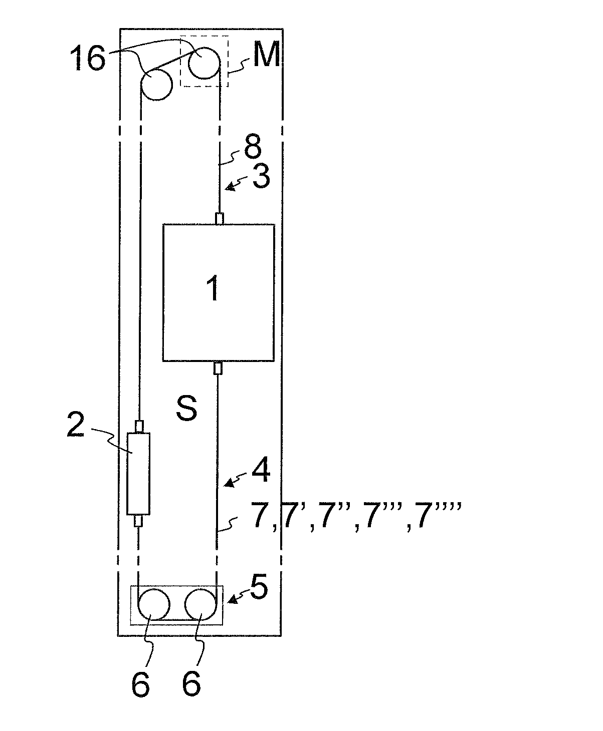
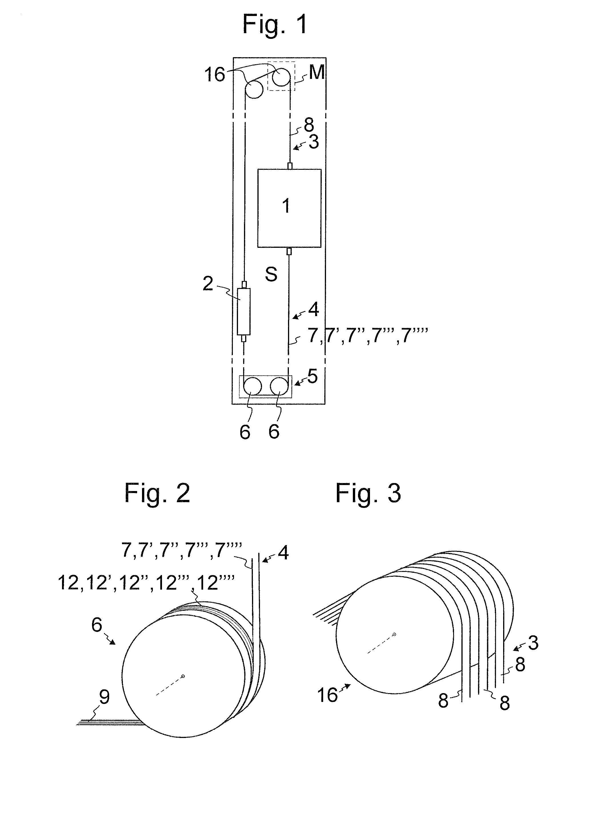
[0037]FIG. 1 illustrates an elevator according to a preferred embodiment. The elevator comprises elevator units, including an elevator car 1 and a counterweight 2, arranged to travel vertically in an elevator hoistway S. The elevator comprises a first roping 3 between the elevator car 1 and counterweight 2 for suspending the elevator car 1 and the counterweight 2. In the preferred embodiment the ends of the first roping 3 are fixed to the elevator car 1 and counterweight 2. Accordingly, it suspends these elevator units with 1:1 suspension ratio. The first roping 3 passes around a rope wheel 16 mounted stationary in a position above said elevator units 1 and 2. The first roping comprises at least one rope 8, but preferably plurality of ropes 8 as illustrated in FIG. 3. The elevator further comprises a second roping 4 between the elevator car 1 and counterweight 2 suspended to hang from the elevator car 1 and counterweight 2, the second roping 4 comprising at least one rope 7-7″″, but...


PUM


Abstract

An elevator includes an elevator car and a counterweight; a first roping between the elevator car and counterweight and including at least one rope; a second roping between the elevator car and counterweight and including at least one rope; and a rope wheel arrangement, having at least one rope wheel, around which the at least one rope of the second roping passes. The longitudinal force transmission capability of the at least one rope of the second roping is based essentially on non-metallic fibers and is a belt-like rope having at least one contoured side provided with guide rib(s) and/or guide groove(s) oriented in the longitudinal direction of the rope, the side being fitted to pass against a contoured circumference of a rope wheel of the rope wheel arrangement, the circumference being provided with guide rib(s) and/or guide groove(s) so as to form a counterpart for the contoured side of the rope.

Description

FIELD OF THE INVENTION[0001]The invention relates to an elevator. The elevator is particularly meant for transporting passengers and / or goods.BACKGROUND OF THE INVENTION[0002]Elevators typically have a suspension roping between the elevator car and the counterweight which roping passes around a rope wheel mounted stationary in some suitable position above said elevator units. Additionally, the elevator may need to be provided with another roping (later referred to as a second roping) between the elevator car and the counterweight suspended to hang from the elevator car and the counterweight. This type of arrangement is normally used to provide compensation for the weight of the hoisting roping. Particularly, in this way the unbalance caused by the hoisting roping and occurring when the elevator car is run to its extreme position can be eliminated. In this case, the second roping can hang freely in the shaft and no rope wheel is necessary to guide it. The second roping may also be us...

Claims


Application Information

Patent Timeline
Patent Type & Authority Applications(United States)
IPC IPC(8): B66B11/00
CPCB66B11/008B66B7/062B66B11/0065B66B7/10D07B2501/2007
Inventor VALJUS, PETTERIPELTO-HUIKKO, RAIMO
Owner KONE CORP
Why Eureka
Try Eureka