Circuit for adjusting frequency of crystal oscillator

a crystal oscillator and frequency technology, applied in oscillation generators, resonance circuit tuning, angle modulation details, etc., can solve problems such as the change of the capacitance of new capacitors

Inactive Publication Date: 2014-07-03
HONG FU JIN PRECISION IND (SHENZHEN) CO LTD +1
View PDF3 Cites 1 Cited by
  • Summary
  • Abstract
  • Description
  • Claims
  • Application Information

AI Technical Summary

Problems solved by technology

However, capacitance of the new capacitors may cha

Method used


Image

  • Circuit for adjusting frequency of crystal oscillator
  • Circuit for adjusting frequency of crystal oscillator
  • Circuit for adjusting frequency of crystal oscillator

Examples


Embodiment Construction

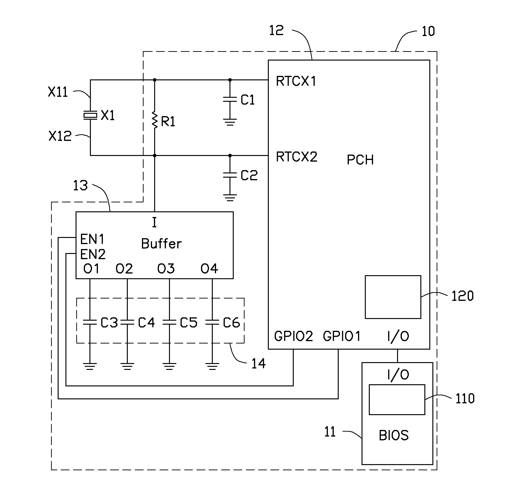
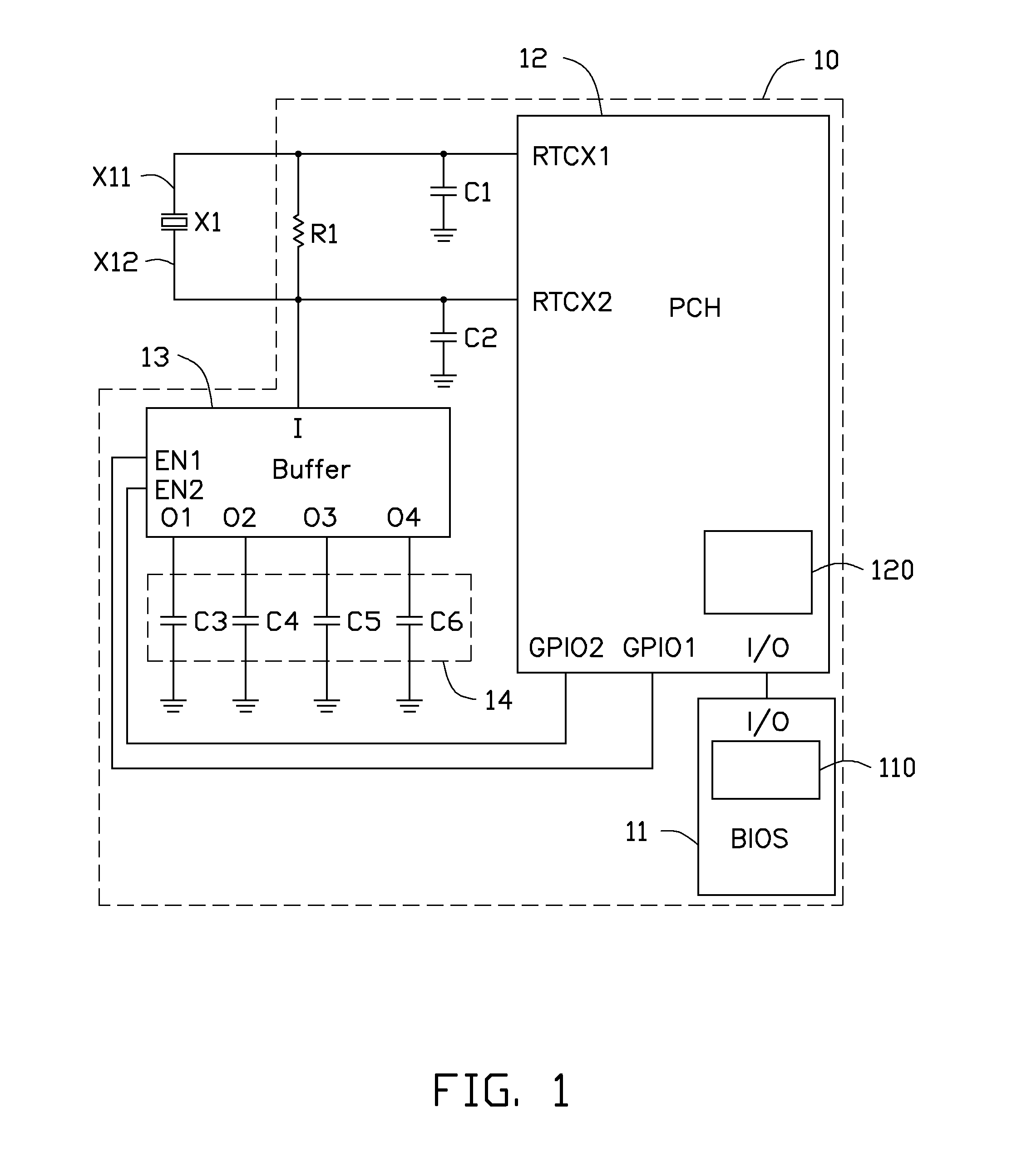
[0009]FIG. 1 is a circuit diagram of an embodiment of a circuit 10 for adjusting frequency of a crystal oscillator X1. The circuit 10 includes a basic input output system (BIOS) 11, a platform controller hub (PCH) 12, a buffer 13, and a capacitor module 14.

[0010]In the embodiment, the BIOS 11 is connected to the PCH 12 by serial peripheral interfaces (SPIs) through input output (I / O) pins of the BIOS 11 and the PCH 12, to make a first register 110 of the BIOS 11 transmit control signals to a second register 120 of the PCH 12. In the embodiment, the control signals output by the first register 110 of the BIOS 11 includes a first digital signal and a second digital signal. A first general purpose input output (GPIO) pin GPIO1 of the PCH 12 and a second GPIO pin GPIO2 of the PCH 12 receive the first digital signal and the second digital signal, respectively, from the second register 120 of the PCH 12, and output the first digital signal and the second digital signal to the buffer 13.

[0...


PUM


Abstract

A circuit for adjusting frequency of a crystal oscillator includes a basic input output system (BIOS), a platform controller hub (PCH), a buffer, and a capacitor module with a number of capacitors. The crystal oscillator is connected to clock pins of the PCH. An input pin of the buffer is connected to the crystal oscillator. A first end of the each of the capacitors is connected to an output pin of the buffer. A second end of the each of the capacitors is grounded. The buffer includes two enable pins and a control unit controlled by the enable pins. The enable pins of the buffer receive a control signal from the PCH according to the BIOS, and control the control unit to appoint the corresponding capacitor of the capacitor module to be connected to the input pin of the buffer.

Description

BACKGROUND[0001]1. Technical Field[0002]The present disclosure relates to a circuit for adjusting frequency of a crystal oscillator.[0003]2. Description of Related Art[0004]Frequency of a crystal oscillator needs to be precisely tuned for electronic devices. The frequency of the crystal oscillator is usually tuned using two capacitors soldered to opposite ends of the crystal oscillator. If the frequency changes over time, the oscillator is retuned by replacing the capacitors. However, capacitance of the new capacitors may change as it can be affected by the soldering process.[0005]Therefore, there is need for improvement in the art.BRIEF DESCRIPTION OF THE DRAWINGS[0006]Many aspects of the present disclosure can be better understood with reference to the following drawing(s). The components in the drawing(s) are not necessarily drawn to scale, the emphasis instead being placed upon clearly illustrating the principles of the present disclosure. Moreover, in the drawing(s), like refer...

Claims


Application Information

Patent Timeline
IPC IPC(8): H03L7/00
CPCH03L7/00H03J2200/10H03B5/36H03B2201/0208H03B2201/0266
Inventor ZHOU, WUGAO, YANG
Owner HONG FU JIN PRECISION IND (SHENZHEN) CO LTD
Why Eureka
Try Eureka