Matrix model estimation time synchronization method based on wireless network clustering topology

A matrix model and wireless network technology, applied in network topology, wireless communication, synchronization devices, etc., can solve problems such as clock drift, clock offset, and clock synchronization protocol obstacles, so as to improve synchronization accuracy, reduce energy consumption, and improve real-time sexual effect

Active Publication Date: 2021-06-25
CHONGQING UNIV OF POSTS & TELECOMM
View PDF17 Cites 1 Cited by
  • Summary
  • Abstract
  • Description
  • Claims
  • Application Information

AI Technical Summary

Problems solved by technology

[0003] The change of the wireless sensor network node itself (node ​​movement, failure, failure, new node joining, etc.) broadcast limitations, the limitation of the distance between the nodes, and the half-duplex communication mode of the wireless node, resulting in complex and changeable communication topology between nodes. Due to its own defects and the uncertainty generated by nodes in the transmission process, the existing clock synchronization protocol has great obstacles in the launch of certain applications.
Due to the interference change of the crystal oscillator frequency of the sensor node by external factors, the clocks of different nodes have different clock frequencies, resulting in clock drift and clock offset during data transmission, and the nodes in the network cannot transmit data accurately and effectively

Method used


Image

  • Matrix model estimation time synchronization method based on wireless network clustering topology
  • Matrix model estimation time synchronization method based on wireless network clustering topology
  • Matrix model estimation time synchronization method based on wireless network clustering topology

Examples


Embodiment Construction

[0091] Embodiments of the present invention are described below through specific examples, and those skilled in the art can easily understand other advantages and effects of the present invention from the content disclosed in this specification. The present invention can also be implemented or applied through other different specific implementation modes, and various modifications or changes can be made to the details in this specification based on different viewpoints and applications without departing from the spirit of the present invention. It should be noted that the diagrams provided in the following embodiments are only schematically illustrating the basic concept of the present invention, and the following embodiments and the features in the embodiments can be combined with each other in the case of no conflict.

[0092] Wherein, the accompanying drawings are for illustrative purposes only, and represent only schematic diagrams, rather than physical drawings, and should...


PUM


Abstract

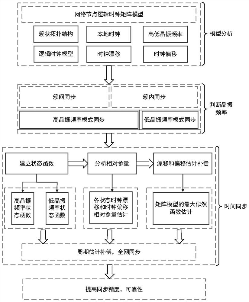
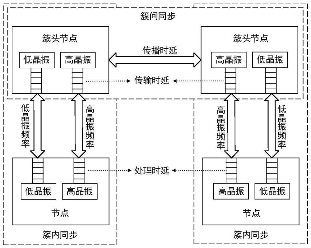
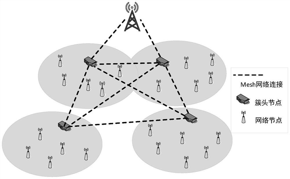
The invention relates to a matrix model estimation time synchronization method based on wireless network clustering topology, and belongs to the technical field of wireless sensor network communication. The method comprises the following steps: S1, deploying network nodes, constructing a clustered topological structure, analyzing states of the nodes in different crystal oscillator frequency working modes, and establishing a logic clock model for matrix estimation; S2, according to the clustered topological structure, dividing the sychronization into inter-cluster synchronization and intra-cluster synchronization, selecting a high crystal oscillator frequency mode or a low crystal oscillator frequency mode, and estimating a clock drift relative parameter and a clock offset relative parameter through state functions established by different crystal oscillator frequencies; S3, respectively estimating the clock drift and the clock offset of the high and low crystal oscillator frequency modes by adopting maximum likelihood estimation through the estimated clock drift relative parameter and the estimated clock offset relative parameter, and periodically compensating the clock drift and the clock offset. According to the invention, the communication problem of the network nodes in different crystal oscillator frequency modes is effectively solved, and the network reliability and the synchronization precision are improved.

Description

technical field [0001] The invention belongs to the technical field of wireless sensor network communication, and relates to a matrix model estimation time synchronization method based on wireless network cluster topology. Background technique [0002] In recent years, the development of wireless sensor networks has become faster and faster, and the application fields have become more and more extensive. The network nodes are affected by various external factors, and the instability of network topology has become a key problem that needs to be solved urgently for time synchronization. The various requirements of various nodes distributed in the wireless sensor network, such as data collection time, time division multiple access, cooperative sleep, data fusion, flow control and other network control, require precise node time synchronization. Since there is a certain deviation between the clocks of different nodes after the network is formed, it is necessary to use clock sync...

Claims


Application Information

Patent Timeline
Patent Type & Authority Applications(China)
IPC IPC(8): H04W56/00H04W84/18
CPCH04W56/001H04W84/18
Inventor 徐国超吴禹霜杨登鑫高铭
Owner CHONGQING UNIV OF POSTS & TELECOMM
Why Eureka
Try Eureka