Communication System Capable of Measuring Crosstalk in Legacy Line

a communication system and legacy communication technology, applied in the field of electronic devices, can solve the problems of unfavorable data transmission, unfavorable data transmission, and interference between lines, and achieve the effect of receiving data, and reducing the number of receivers

Active Publication Date: 2014-07-03
AVAGO TECH INT SALES PTE LTD
View PDF6 Cites 11 Cited by
  • Summary
  • Abstract
  • Description
  • Claims
  • Application Information

AI Technical Summary

Problems solved by technology

Because the lines are loaded differently, the lines will interfere with one another in the form of crosstalk.
The crosstalk may be generated by undesired capacitive, inductive, or conductive coupling between the lines, and will cause an undesired effect on the information being transmitted in those lines.
While being transmitted through particular line, the crosstalk generated in the line from the other lines may cause a shift in the amplitude and / or phase of the signal, thereby causing a receiver of the data to misread the binary data contained within the signal as corresponding to a different location of the quadrature constellation.
In other words, crosstalk can cause bit errors in transmitted data or limit distance between two points of a constellation and therefore limit achievable signal-to-noise ratio (SNR).
However; legacy lines (e.g., lines following earlier DSL standards) lack this capability.
Therefore, it is difficult to employ the G.vector crosstalk measurement procedure in the legacy line.
However, when performed in this manner, prior to the handshake, the impedance seen by the legacy line may be different than that seen during showtime (e.g., data transmission) mode, which may lead to an incorrect calculation of crosstalk.

Method used


Image

  • Communication System Capable of Measuring Crosstalk in Legacy Line
  • Communication System Capable of Measuring Crosstalk in Legacy Line
  • Communication System Capable of Measuring Crosstalk in Legacy Line

Examples


Embodiment Construction

[0017]The following Detailed Description refers to accompanying drawings to illustrate exemplary embodiments consistent with the disclosure. References in the Detailed Description to “one exemplary embodiment,”“an exemplary embodiment,”“an example exemplary embodiment,” etc., indicate that the exemplary embodiment described may include a particular feature, structure, or characteristic, but every exemplary embodiment may not necessarily include the particular feature, structure, or characteristic. Moreover, such phrases are not necessarily referring to the same exemplary embodiment. Further, when a particular feature, structure, or characteristic is described in connection with an exemplary embodiment, it is within the knowledge of those skilled in the relevant art(s) to affect such feature, structure, or characteristic in connection with other exemplary embodiments whether or not explicitly described.

[0018]The exemplary embodiments described herein are provided for illustrative pur...


PUM


Abstract

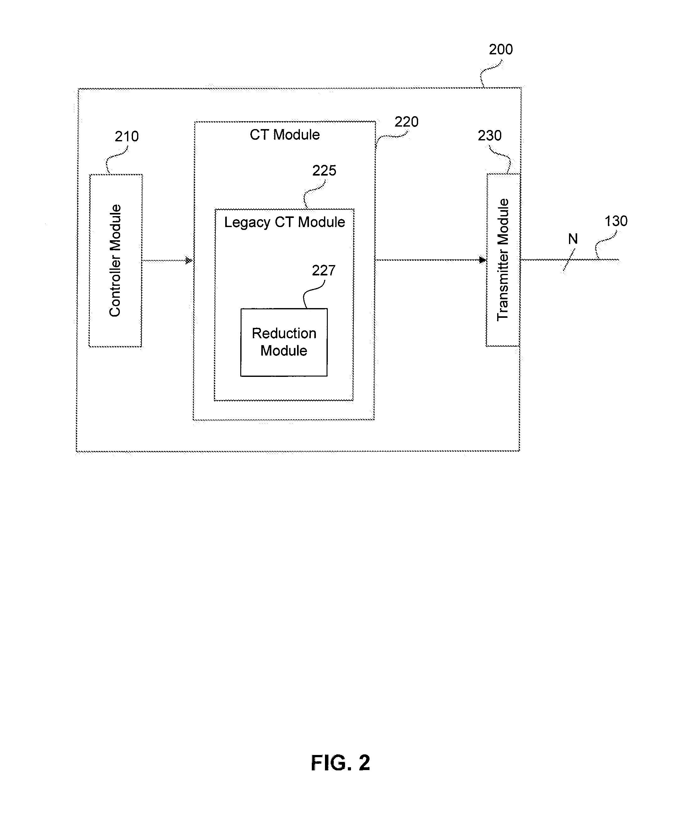
A DSL transmitter and receiver are disclosed that are capable of accurately measuring crosstalk in G.vector-compliant DSL lines resulting from a legacy line. During crosstalk measurement, the legacy line can be placed in a showtime mode. Once in showtime mode, a data signal designated for the legacy line is reduced in power spectrum density and / or spectrum to reduce its effects on crosstalk measurements. An O-P-Vector-1 signal is then superposed on the reduced data signal, and the resulting test signal is transmitted over the legacy line while sync signals are transmitted over neighboring G.vector lines. The receiver can then accurately measure the crosstalk on the neighboring lines, and report back to the transceiver for adjustments. A similar configuration can be performed in a diagnostic mode of the legacy line.

Description

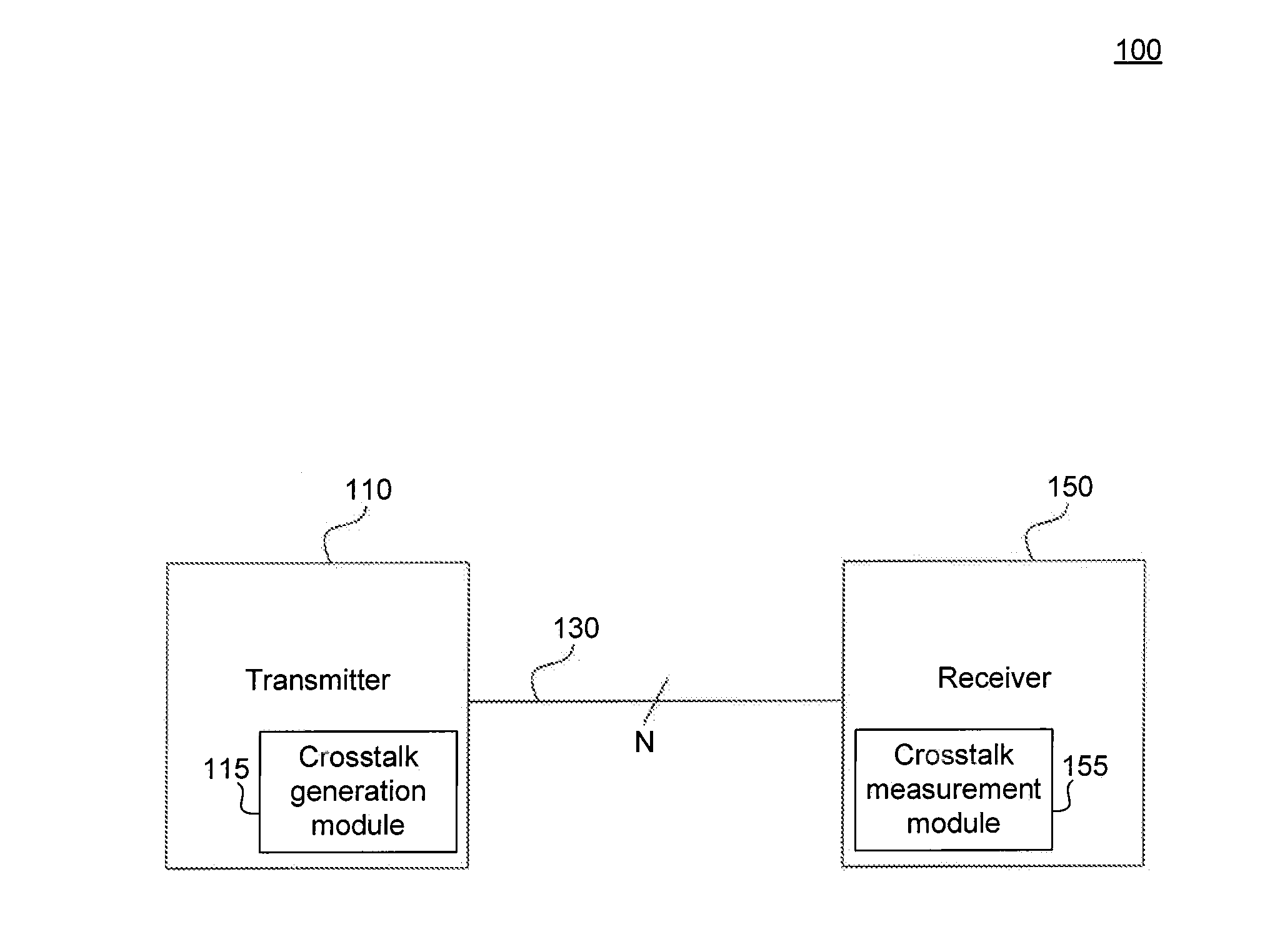
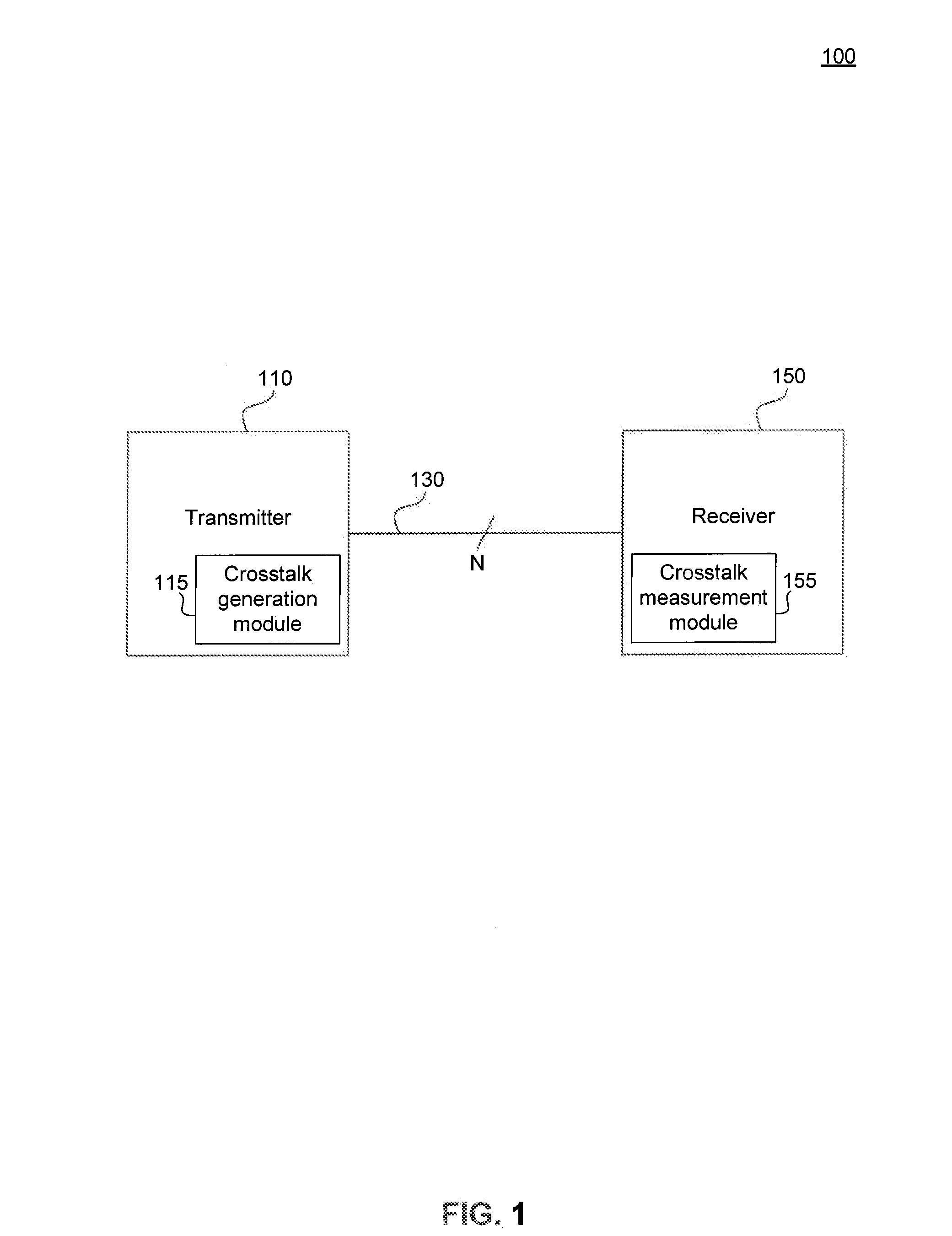
BACKGROUND[0001]1. Technical Field[0002]The disclosure relates to an electronics device, and more specifically relates to a transmitter and receiver in a DSL communication system capable of measuring crosstalk in a legacy communication line.[0003]2. Related Art[0004]In DSL (Digital Subscriber Line) communications, a transmitter and receiver communicate with one another over a plurality of “lines.” Each line includes a twisted pair of wires for communicating information. Each of the lines is typically loaded with different information so as to allow for parallel communication, and increased throughput.[0005]Because the lines are loaded differently, the lines will interfere with one another in the form of crosstalk. The crosstalk may be generated by undesired capacitive, inductive, or conductive coupling between the lines, and will cause an undesired effect on the information being transmitted in those lines.[0006]For example, data communicated in DSL is often transmitted as a QAM (Qu...

Claims


Application Information

Patent Timeline
Patent Type & Authority Applications(United States)
IPC IPC(8): H04B3/32
CPCH04B3/32H04B3/487H04L25/085H04M3/18H04M3/304H04M3/34
Inventor CASSIERS, RAPHAEL PAULPEETERS, MIGUEL
Owner AVAGO TECH INT SALES PTE LTD
Why Eureka
Try Eureka