Frequency sweep signal generator, frequency component analysis apparatus, radio apparatus, and frequency sweep signal generating method
a frequency component analysis and frequency component technology, applied in pulse automatic control, digital transmission, resonance circuit details, etc., can solve the problems of large power consumption, large frequency error, and difficulty in increasing the processing speed of frequency component analysis, and achieve the effect of reducing frequency error
- Summary
- Abstract
- Description
- Claims
- Application Information
AI Technical Summary
Benefits of technology
Problems solved by technology
Method used
Image
Examples
first exemplary embodiment
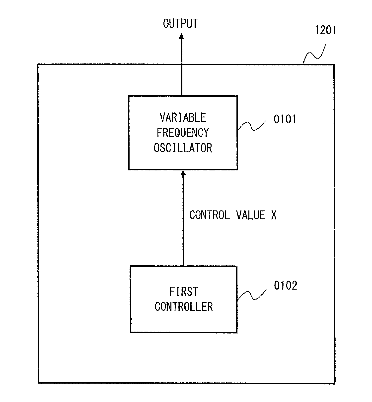
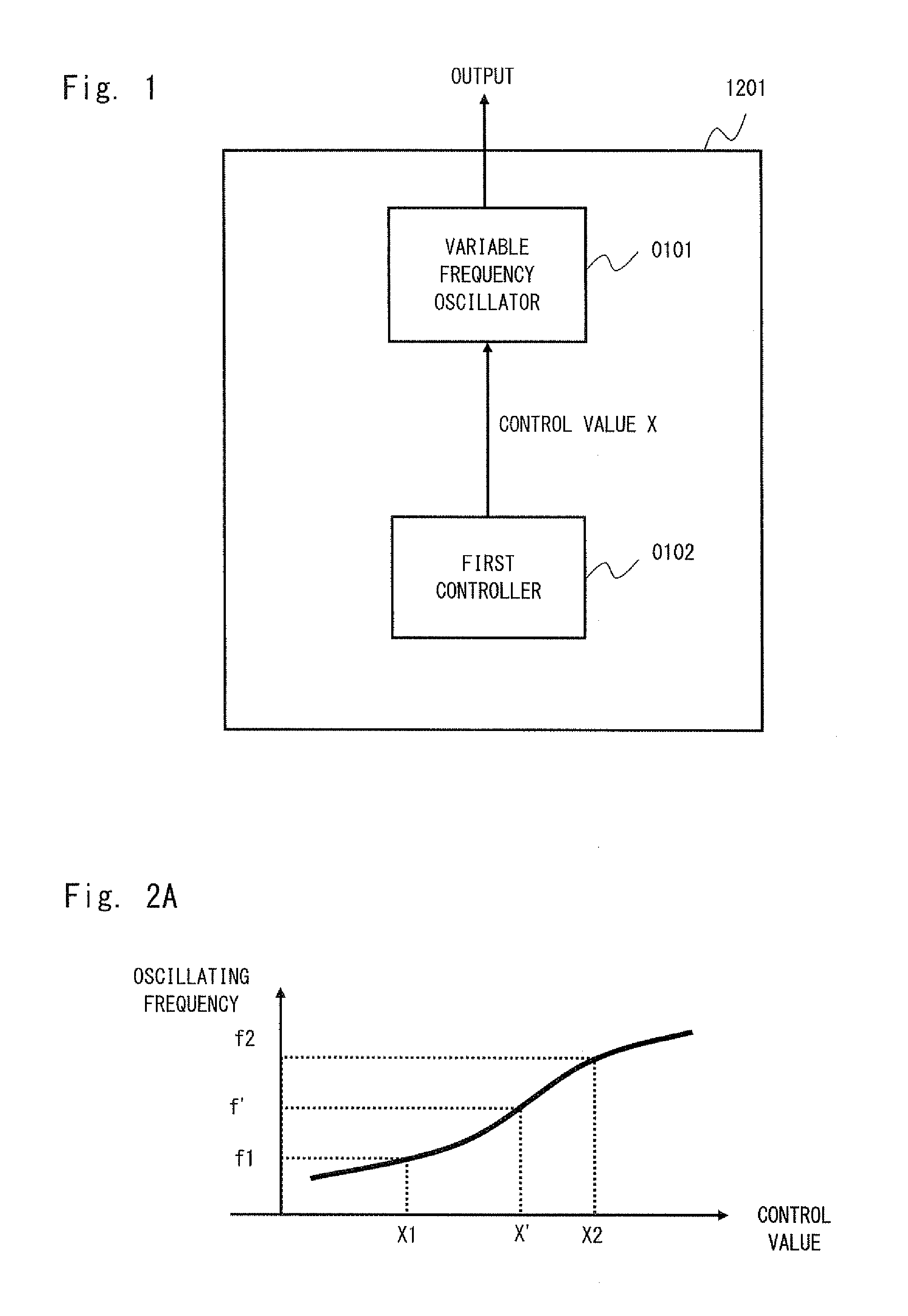
[0032]Exemplary embodiments according to the present invention are explained hereinafter with reference to the drawings. Note that the same symbols are assigned to the same elements throughout all the drawings explained below, and explanation is omitted as necessary. Firstly, a configuration example of a frequency sweep signal generator according to a first exemplary embodiment of the present invention is explained with reference to FIG. 1. The frequency sweep signal generator includes a variable frequency oscillator 0101 and a first controller 0102.
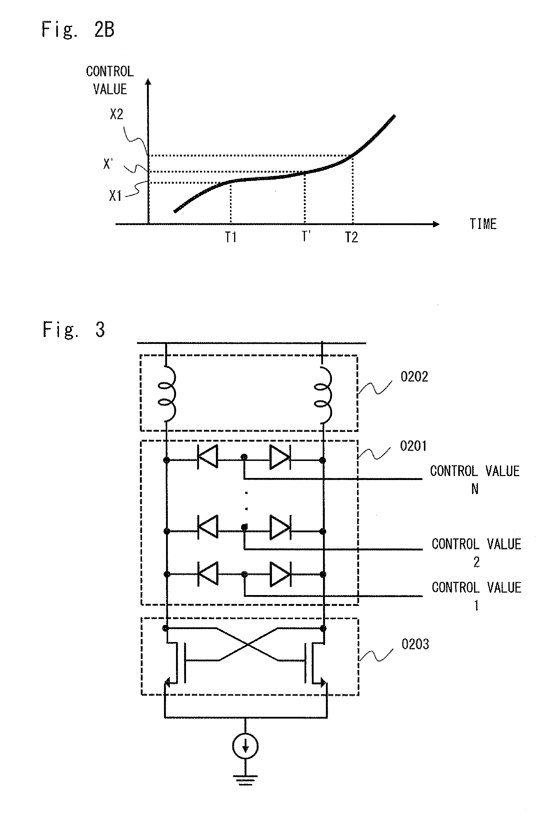
[0033]The variable frequency oscillator 0101 changes an oscillating frequency according to the change of an input control value. For example, a voltage value may be used as the control value. In this case, the variable frequency oscillator 0101 generates an oscillating frequency corresponding to an input voltage value. Further, the voltage value may be analog data or digital data that is obtained by converting analog data into discrete d...
second exemplary embodiment
[0047]Next, a configuration example of a frequency sweep signal generator according to a second exemplary embodiment of the present invention is explained with reference to FIG. 5. The frequency sweep signal generator according to the second exemplary embodiment includes a variable frequency oscillator 0101, a first controller 0102, a second controller 0501, and a selector 0502.
[0048]The second controller 0501 outputs a value corresponding to a difference between the frequency or the phase of the output signal of the variable frequency oscillator 0101 and the frequency or the phase of a reference signal, to the selector 0502 as a second control value. In this manner, the second controller 0501 serves as one of the components forming the phase-locked loop, and can determine the relation between the oscillating frequency output from the variable frequency oscillator 0101 and the second control value with high accuracy.
[0049]The selector 0502 receives the first control value from the f...
third exemplary embodiment
[0058]Next, a configuration example of a frequency sweep signal generator according to a third exemplary embodiment of the present invention is explained with reference to FIG. 8. The frequency sweep signal generator according to the third exemplary embodiment includes a variable frequency oscillator 0101, a first controller 0102, a second controller 0501, a selector 0502, and an integrator 0801.
[0059]When frequency sweeping is performed at a high speed by using the first controller 0102, the integrator 0801 increases the control value from the initial value X for the control value output from the first controller 0102 at a fixed rate and outputs the gradually-increasing control value to the variable frequency oscillator 0101. The integrator 0801 stops increasing the control value when the control value reaches the control value indicating the final value for the frequency sweeping range. In this manner, upon receiving the control value, which is the initial value for the predetermi...
PUM
 Abstract
Description
Claims
Application Information
 - R&D
- Intellectual Property
- Life Sciences
- Materials
- Tech Scout
- Unparalleled Data Quality
- Higher Quality Content
- 60% Fewer Hallucinations
Browse by: Latest US Patents, China's latest patents, Technical Efficacy Thesaurus, Application Domain, Technology Topic, Popular Technical Reports.
© 2025 PatSnap. All rights reserved.Legal|Privacy policy|Modern Slavery Act Transparency Statement|Sitemap|About US| Contact US: help@patsnap.com


