
Methods and systems for a digital frequency locked loop for multi-frequency clocking of a multi-core processor

Active Publication Date: 2009-03-10
IBM CORP
View PDF6 Cites 9 Cited by
  • Summary
  • Abstract
  • Description
  • Claims
  • Application Information

AI Technical Summary

Benefits of technology

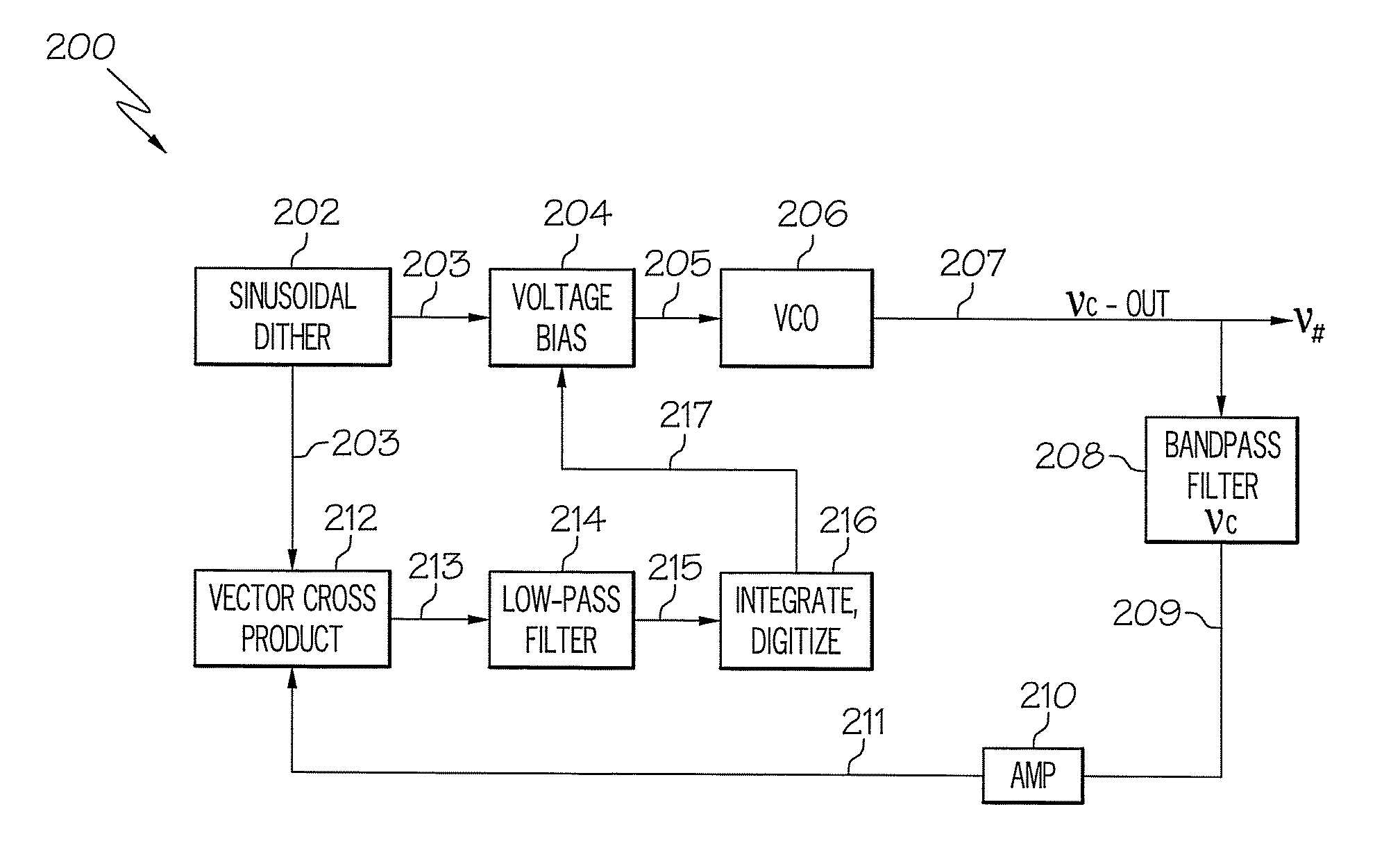
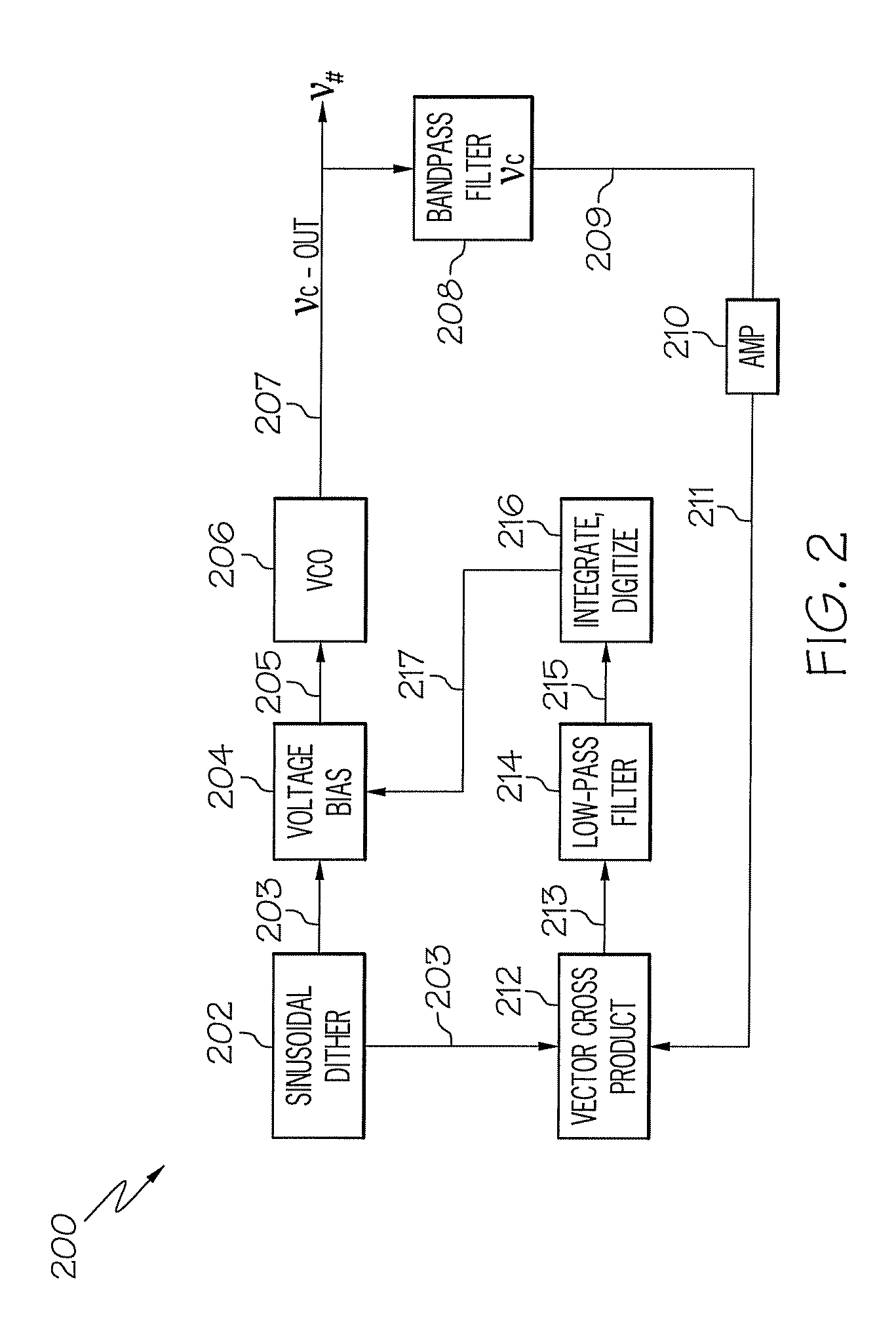
[0007]Further embodiments include a system for a digital frequency locked loop in a multi-core processor. The system includes a dither modulator to generate a dither modulation frequency. The system also includes error-signal decision logic to control mixing a digital correction signal with the dither modulation frequency to produce an output frequency, where the output frequency provides a clock signal to a core in the multi-core processor. The system additionally includes a feedback path isolating frequency content of the output signal with respect to a target frequency, where the isolated frequency content is input to the error-signal decision logic to reduce frequency error between the output signal and the target frequency.

Problems solved by technology

Existing clock distribution trees are impractical to design, fabricate and yield for microprocessors including a large numbers of processing cores in newly emerging multi-core micro-architectures which are increasing processor speed to gain additional performance.
PLLs can suffer from common phase-noise and susceptibility to jitter and skew, known as “skitter”.
Capture, lock, and voltage fluctuations may destabilize PLLs.
Additionally, PLLs typically rely on a single point solution, where a control circuit attempts to drive phase-error to a null or zero value, which can increase the chance of a false lock while also requiring a continuous reference clock to maintain a lock and generate an output clock.

Method used


Image

  • Methods and systems for a digital frequency locked loop for multi-frequency clocking of a multi-core processor
  • Methods and systems for a digital frequency locked loop for multi-frequency clocking of a multi-core processor
  • Methods and systems for a digital frequency locked loop for multi-frequency clocking of a multi-core processor

Examples


Embodiment Construction

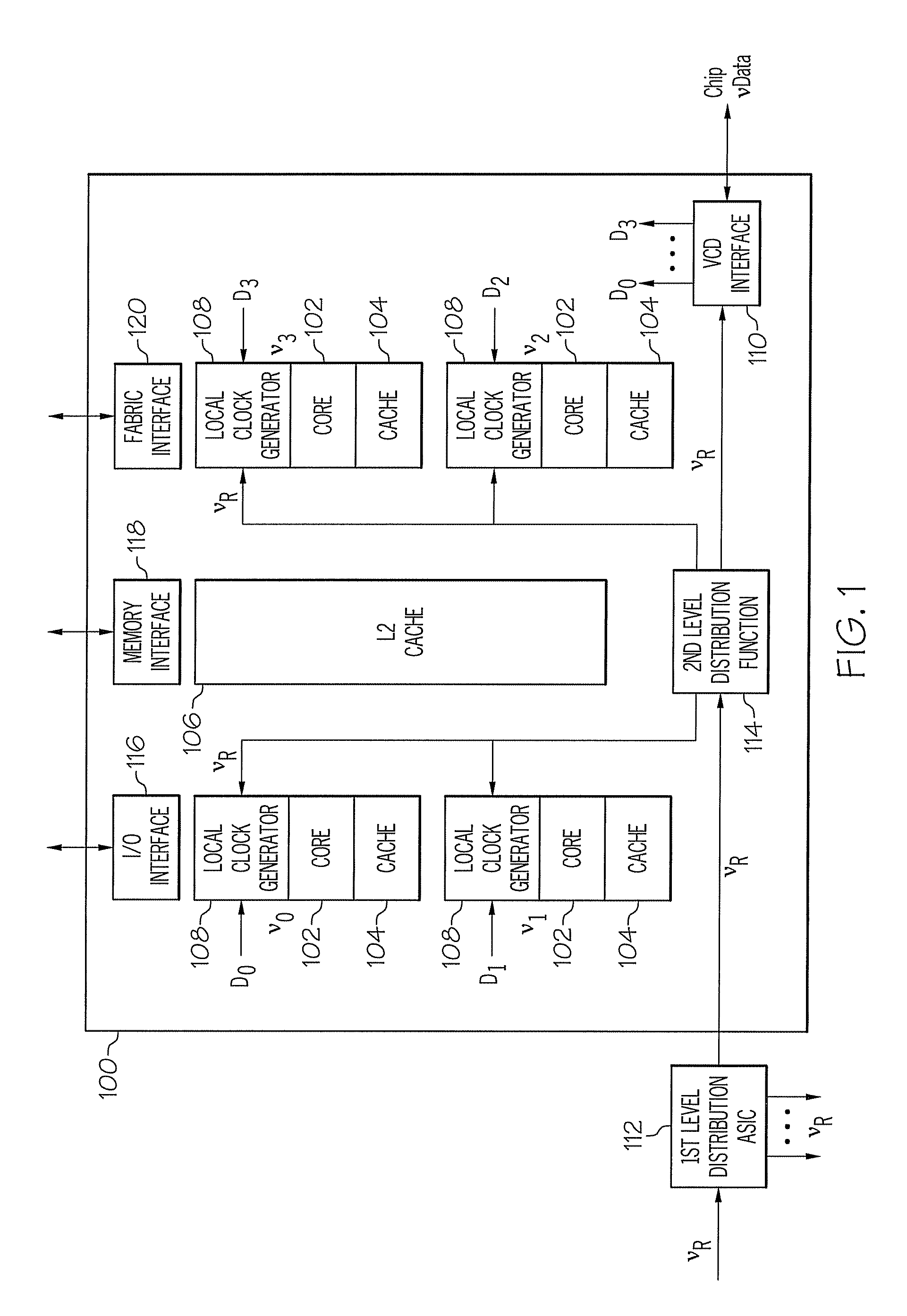
[0020]Exemplary embodiments provide methods and systems for a digital frequency locked loop (FLL) to support multi-frequency clocking in a multi-core processor system. A “digital FLL” refers to applying digital signal processing and / or digital control logic to an FLL. An FLL employs a closed loop feedback control technique to maintain a desired output frequency. In exemplary embodiments, an FLL uses output of a digital frequency filter to equalize two sideband signals, which directly indicates if the clock frequency is too high or too low, rather than a phase error signal that is minimized in a phase locked loop (PLL). Unlike a PLL, an FLL will not lock onto harmonics of a reference frequency. Using an FLL enables a clock distribution system with a low-speed reference clock provided to a microprocessor chip to control the high frequency target clock. This is advantageous, since propagating high-speed clocks over long distances may be an inhibitor for microprocessor chip size, comple...


PUM


Abstract

A method and systems for a digital frequency locked loop in a multi-core processor are provided. The method includes applying a dither modulation signal at a dither modulation frequency to modulate an output frequency to provide a clock signal to a core of the multi-core processor. The method further includes filtering a feedback signal of the output frequency with respect to a target frequency. The method additionally includes determining a frequency error in the filtered feedback signal as a function of alignment of the output frequency to the target frequency, and adjusting the output frequency in response to the frequency error.

Description

CROSS-REFERENCE TO RELATED APPLICATIONS[0001]This application contains subject matter related to the subject matter of the following co-pending application, which is hereby incorporated herein by reference in its entirety: U.S. patent application Ser. No. 11 / 873,458, entitled METHODS AND SYSTEMS FOR DIGITALLY CONTROLLED MULTI-FREQUENCY CLOCKING OF MULTI-CORE PROCESSORS, filed on Oct. 17, 2007.BACKGROUND OF THE INVENTION[0002]The present disclosure relates generally to computer system clocking, and, in particular, to a digital frequency locked loop for multi-frequency clocking in a multi-core processor system.[0003]Existing clock distribution trees are impractical to design, fabricate and yield for microprocessors including a large numbers of processing cores in newly emerging multi-core micro-architectures which are increasing processor speed to gain additional performance. Complementary metal oxide semiconductor (CMOS) gate-leakage power or passive power is increasingly dominating ...

Claims


Application Information

Patent Timeline
IPC IPC(8): H03L7/06
CPCH03L7/093H03L7/18H03L2207/50
Inventor JACOBOWITZ, LAWRENCESTIGLIANI, JR., DANIEL J.
Owner IBM CORP
Learn More