
Physical-layer channel bonding

a physical layer and channel technology, applied in the field of communication systems, can solve the problems of significant challenges in the implementation of an epoc network or similar network over a coax cable plan

Inactive Publication Date: 2014-07-03
QUALCOMM INC
View PDF2 Cites 19 Cited by
  • Summary
  • Abstract
  • Description
  • Claims
  • Application Information

AI Technical Summary

Benefits of technology

The patent text describes a method and system for transmitting data over a network using multiple channels. The system includes a coax cable plant with multiple types of network units that use different frequency bands. The challenge is to efficiently bond the channels in a way that allows for seamless communication between the network units. The patent describes a solution that uses a fixed delay in the physical layer to direct transmit packets to the network units, allowing for the efficient use of multiple PMEs and the generation of transmit signals on distinct channels. The technical effect of this invention is to improve the efficiency and reliability of transmitting data over a network using multiple channels.

Problems solved by technology

Implementing an EPoC network or similar network over a coax cable plant presents significant challenges.

Method used


Image

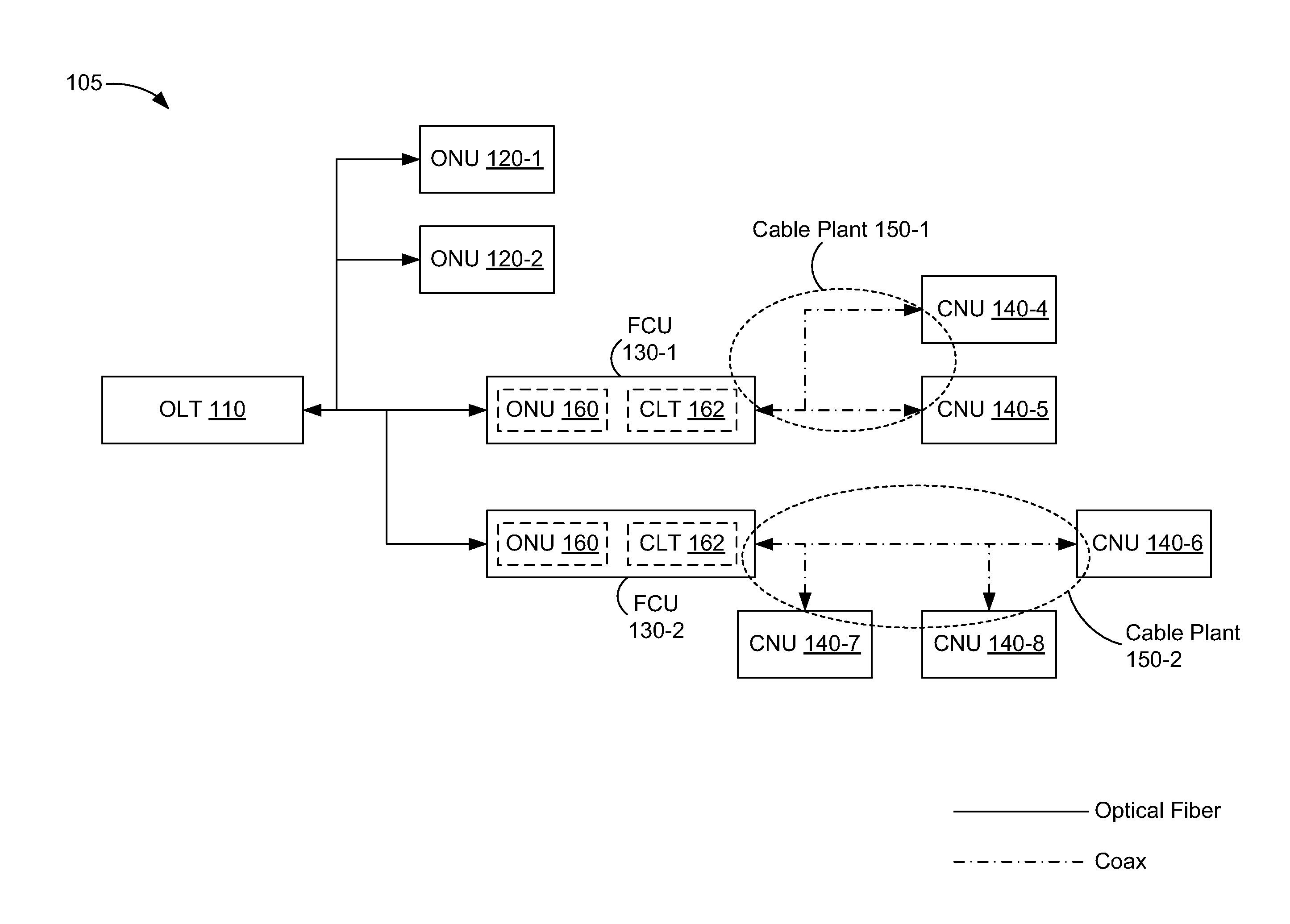
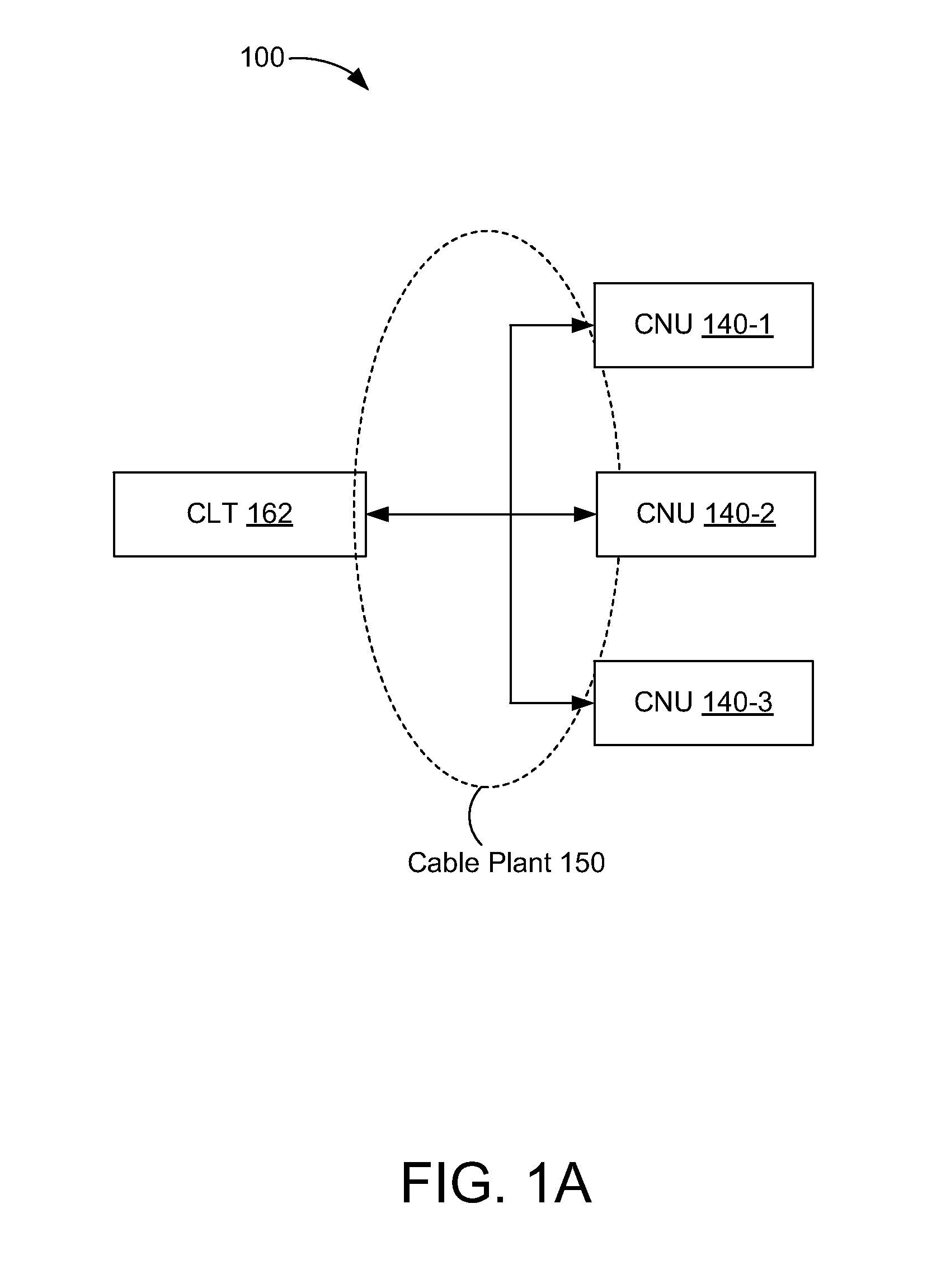
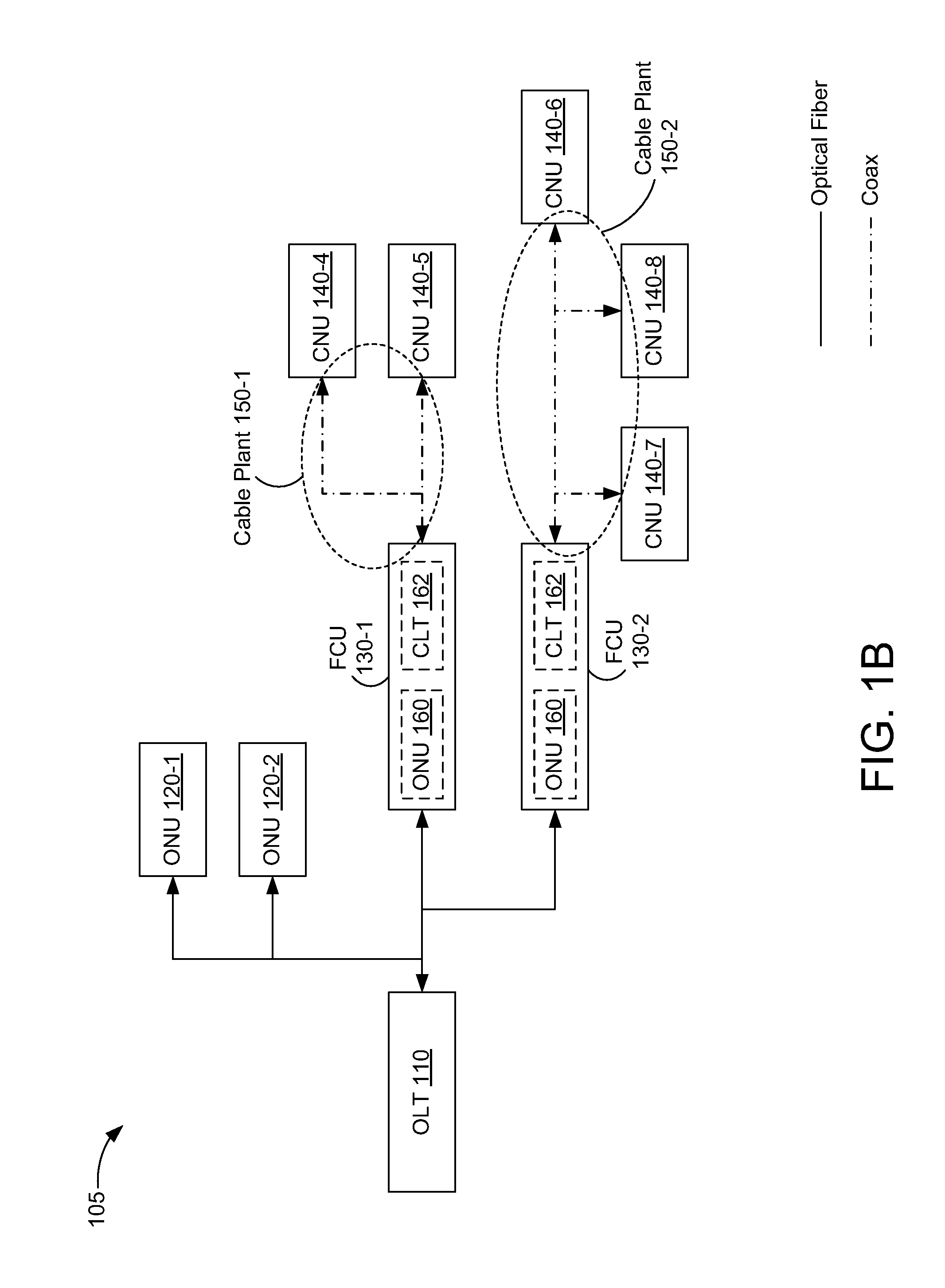
  • Physical-layer channel bonding
  • Physical-layer channel bonding
  • Physical-layer channel bonding

Examples


Embodiment Construction

[0020]Embodiments are disclosed in which packets are directed in a physical layer (PHY) with a substantially fixed delay.

[0021]In some embodiments, a network device includes a plurality of physical-media entities (PMEs), each corresponding to a distinct channel, to generate transmit signals based on transmit packets received over a media-independent interface. The network device also includes a channel-bonding sublayer (CBS) to direct the transmit packets from the media-independent interface to respective PMEs of the plurality of PMEs. The channel-bonding sublayer has a substantially fixed delay between the media-independent interface and the plurality of PMEs for the transmit packets.

[0022]In some embodiments, a method of operating a network device includes directing transmit packets from a media-independent interface to respective physical-media entities (PMEs) of a plurality of PMEs. A delay associated with the directing is substantially fixed. The method also includes generating...


PUM


Abstract

A network device includes a plurality of physical-media entities (PMEs), each corresponding to a distinct channel, to generate transmit signals based on transmit packets received over a media-independent interface. The network device also includes a channel-bonding sublayer to direct the transmit packets from the media-independent interface to respective PMEs of the plurality of PMEs. The channel-bonding sublayer has a substantially fixed delay between the media-independent interface and the plurality of PMEs for the transmit packets.

Description

RELATED APPLICATION[0001]This application claims priority to U.S. Provisional Patent Application No. 61 / 748,728, titled “Physical Layer Channel Bonding,” filed Jan. 3, 2013, which is hereby incorporated by reference in its entirety.TECHNICAL FIELD[0002]The present embodiments relate generally to communication systems, and specifically to communication systems that use multiple channels.BACKGROUND OF RELATED ART[0003]The Ethernet Passive Optical Networks (EPON) protocol may be extended over coaxial (coax) links in a cable plant. The EPON protocol as implemented over coax links is called EPoC. Implementing an EPoC network or similar network over a coax cable plant presents significant challenges. For example, multiple types of coax network units (CNUs) may be connected to the cable plant, with each type using a different set of frequency bands. The frequency bands used for communication between a coax line terminal (CLT) and CNUs of a given type may not be contiguous. Also, the CNUs m...

Claims


Application Information

Patent Timeline
Patent Type & Authority Applications(United States)
IPC IPC(8): H04B10/27
CPCH04B10/27H04Q11/0071
Inventor SHELLHAMMER, STEPHEN J.STUPAR, PATRICKVARANESE, NICOLAGARAVAGLIA, ANDREAMONTOJO, JUANPIETSCH, CHRISTIAN
Owner QUALCOMM INC
Learn More