Eureka AIR delivers breakthrough ideas for toughest innovation challenges, trusted by R&D personnel around the world.

Systems and methods for visible light communication

a technology of visible light and communication system, applied in the field of visible light communication system, can solve the problems of adding cost and complexity, and achieve the effects of reducing cost and complexity, and facilitating data recovery within the receiver

Active Publication Date: 2011-03-24
LUTRON TECH CO LLC
View PDF98 Cites 141 Cited by
  • Summary
  • Abstract
  • Description
  • Claims
  • Application Information

AI Technical Summary

Benefits of technology

[0021]In certain embodiments, the visible light communication techniques described herein can be used in combination with existing electronics for LED lights to implement a variety of advantageous lighting control systems and features, such as remote control, daylight harvesting, scheduling, and occupancy sensing in the light are possible at very little additional cost. These lighting control systems further allow a plurality of illumination devices to communicate with each other, remote controllers, and a central controller. Further, the techniques described herein could also be used by a single illumination device and controller, or other devices and applications, as desired. In particular, an AC mains powered controller with a light source that is normally off could communicate information, such as dimming level and color settings, to one or more LED lamps. In contrast with the techniques described herein, control of conventional lighting is typically performed by separate electronic units that communicate with each other over wires or radios, which add cost and complexity.
[0022]Illumination devices described herein preferentially comprise phase locked loops (PLLs) that phase lock to the AC mains and produce the synchronized timing signals for operating the devices. Since other illumination devices in the lighting systems for instance phase lock to the same AC mains signal, all such devices have precisely the same internal timing. With such synchronized timing, communication channels can be formed during which all devices can communicate. Likewise, since the bit level timing of data communication within such channels is precisely synchronized, data recovery within a receiver is substantially easier since the received data timing is known.
[0023]A communication channel is a timeslot that preferentially spans a fraction of an AC mains period (16.67 mSec for 60 Hz) during which all the members of a group of devices stop producing illumination. Higher layers in a communication protocol, such as ZigBee, can dynamically assign individual devices to communicate on different channels. During such timeslots information can be communicated optically between such members when one member produces light modulated with data. During such timeslots when data is not being communicated, ambient light can be measured for daylight harvesting applications and for improving receiver sensitivity.
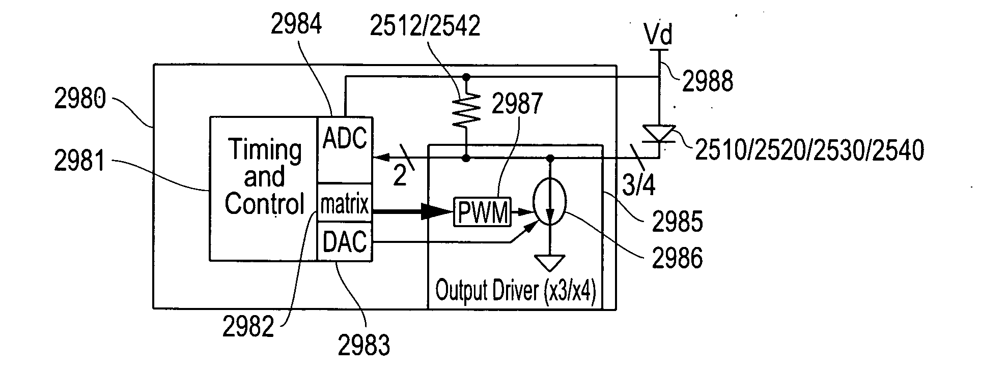
[0024]Preferentially, the illumination devices comprise LEDs for illumination and for transmitting and receiving data to minimize cost and maximize receiver sensitivity. Because white LEDs that comprise a blue LED covered with a phosphor have poor sensitivity to received light, preferentially the illumination devices comprise LEDs with different colors to produce the desired white light. Possible combinations include white and red, or red, yellow, green, and blue, but could include any combination or even a single color provided at least one LED in the illumination device is preferably not phosphor coated. Preferentially, the illumination devices comprise red LEDs for best receiver sensitivity. The additional cost of controlling multicolored LEDs can be reduced or eliminated in lamps that combine the systems and methods described herein with those described in additional embodiments as described herein for calibrating devices using LEDs such as those described herein with respect to the second embodiment, the third embodiment, the seventh embodiment and the eighth embodiment. These embodiments describe in part techniques to precisely control the color of light produced by combinations of different colored LEDs, such as white and red, or red, yellow, green, and blue, and can do so without the need for additional photo-detectors or temperature sensors thereby making such implementations more cost effective.
[0026]The systems and methods disclosed herein address problems with prior systems in part by providing physical layers for lighting control systems for reduced costs and / or relatively insignificant additional costs. Advantageously, the illumination devices and other devices in the lighting system described herein can communicate using the devices already needed for illumination.

Problems solved by technology

In contrast with the techniques described herein, control of conventional lighting is typically performed by separate electronic units that communicate with each other over wires or radios, which add cost and complexity.

Method used


Image

  • Systems and methods for visible light communication
  • Systems and methods for visible light communication
  • Systems and methods for visible light communication

Examples


first embodiment

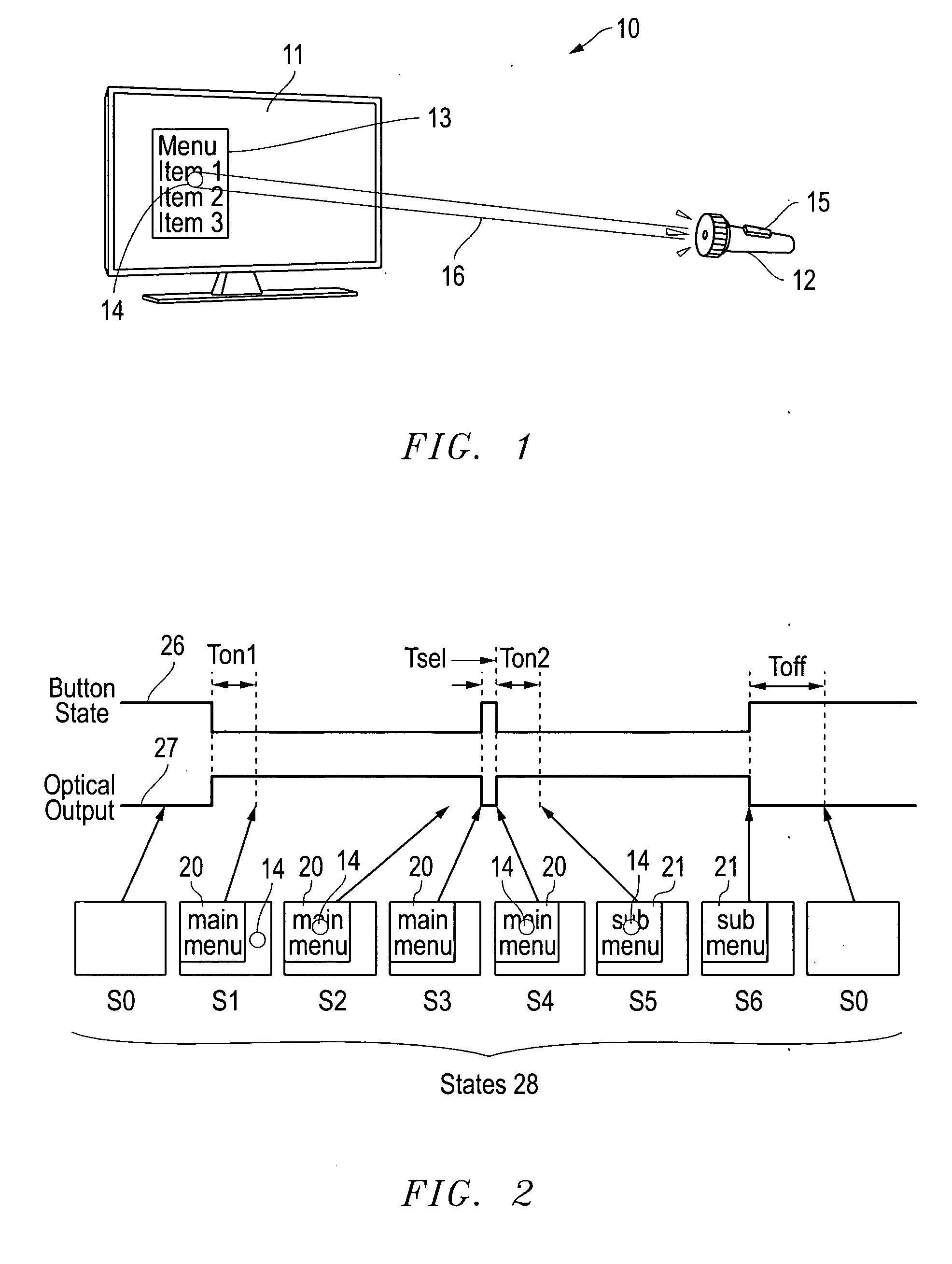
[0126]Display and optical pointer systems and related methods are disclosed that utilize LEDs in a display device to respond to optical signals from optical pointing devices. Various embodiments are described with respect to the drawings below. Other features and variations can also be implemented, if desired, and related systems and methods can be utilized, as well.

[0127]In part, the disclosed embodiments relate to displays with arrays of LEDs and associated pointing devices that communicate with individual LEDs in the arrays using visible light. The LED arrays can produce images directly as in LED billboards and sports arena scoreboards or can produce the backlight for LCD screens for instance. The pointing devices communicate with individual pixels or groups of pixels using a beam of light that may or may not be modulated with data, which is detected by the LEDs in the array that are exposed to the beam. Periodically, the LEDs in an array stop producing light and are configured w...

second embodiment

[0209]Display calibration systems and related methods are also disclosed that use the photo-sensitivity of LEDs to correct for variations between LEDs during initial production and over lifetime for display systems. Various embodiments are described with respect to the drawings below. Other features and variations can also be implemented, if desired, and related systems and methods can be utilized, as well.

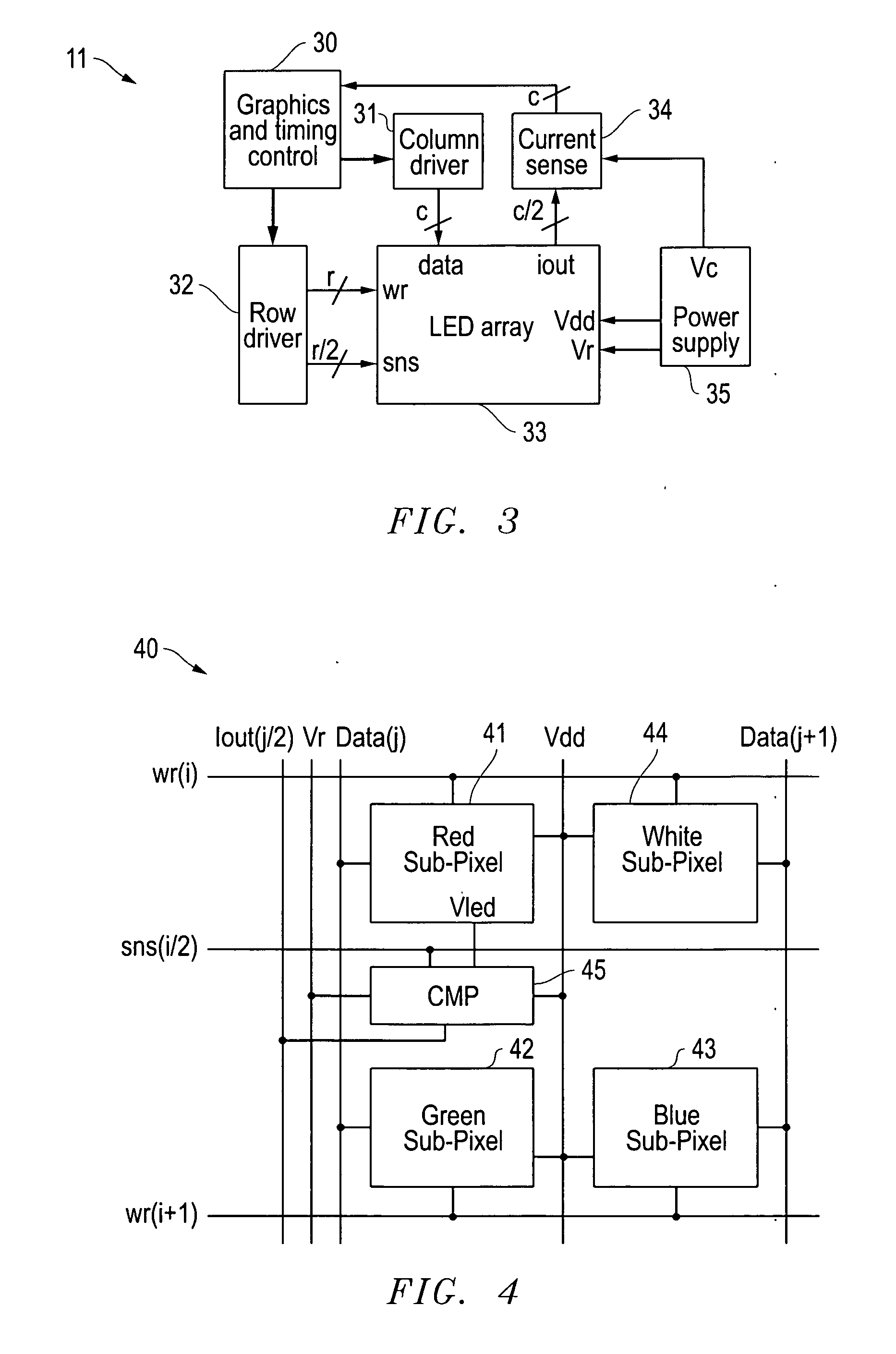
[0210]In part, the disclosed embodiments relate to displays including arrays of LEDs that use the photo-sensitivity of the LEDs to correct for variations between LEDs during initial production and over lifetime of such a display. Such LED arrays can produce images directly as in LED billboards and sports arena scoreboards, and smaller Organic LED (OLED) displays, or can produce the backlight for LCD screens for instance. Variations in LED brightness and color can be compensated for in order for such a display to have uniform color and brightness. Such compensation, which is typica...

third embodiment

[0262]LED calibration systems and related methods are also disclosed that use the photo-sensitivity of LEDs to correct for variations between LEDs during initial production and over the lifetime of systems using LEDs. Various embodiments are described with respect to the drawings below. Other features and variations can also be implemented, if desired, and related systems and methods can be utilized, as well.

[0263]In part, the disclosed embodiments relate to using the photo-sensitivity of an LED to determine emission parameters such as intensity and wavelength. Applications for the disclosed embodiments include solid state lamps, LCD backlights, and LED displays for instance. Variations in LED brightness and wavelength should be compensated for in order for such devices to have uniform color and brightness. Such compensation, which is typically done by measuring the optical output of each individual LED with a camera or purchasing specially tested LEDs, is performed by simply measur...


PUM


Abstract

Systems and methods for visible light communication are disclosed. In part, illumination devices and related systems and methods are disclosed that can be used for general illumination, lighting control systems, or other applications. The illumination devices synchronize preferentially to the AC mains to produce time division multiplexed channels in which control information can be communicated optically by the same light source that is producing illumination. Such illumination devices preferentially comprise LEDs for producing illumination, transmitting data, detecting ambient light, and receiving data, however, other light sources and detectors can be used. The physical layer can be used with a variety of protocols, such as ZigBee, from the Media ACcess (MAC) layer and higher.

Description

RELATED APPLICATIONS[0001]This application claims priority to the following co-pending provisional applications: U.S. Provisional Patent Application Ser. No. 61 / 273,518 filed Aug. 5, 2009 by David J. Knapp and entitled “Display and Optical Pointer Systems and Related Methods;” U.S. Provisional Patent Application Ser. No. 61 / 273,536 filed Aug. 5, 2009 by David J. Knapp and entitled “Display Calibration Systems and Related Methods;” U.S. Provisional Patent Application Ser. No. 61 / 277,871 filed Sep. 30, 2009 by David J. Knapp and entitled “LED Calibration Systems and Related Methods;” U.S. Provisional Patent Application Ser. No. 61 / 281,046 filed Nov. 12, 2009 by David J. Knapp and entitled “LED Calibration Systems and Related Methods;” U.S. Provisional Patent Application Ser. No. 61 / 336,242 filed Jan. 19, 2010 by David J. Knapp and entitled “Illumination Devices and Related Systems and Methods;” and U.S. Provisional Patent Application Ser. No. 61 / 339,273 filed Mar. 2, 2010 by David J. ...

Claims


Application Information

Patent Timeline
Patent Type & Authority Applications(United States)
IPC IPC(8): H04J14/08H04B10/10H05B37/02
CPCH04L12/43H04L2012/40273H04L12/437
Inventor KNAPP, DAVID J.HO, HORACE C.
Owner LUTRON TECH CO LLC
Why Eureka
Eureka Blog
Learn More