Double-valve mechanism

Inactive Publication Date: 2014-07-10
HYPHONE MASCH IND CO LTD
View PDF0 Cites 2 Cited by
  • Summary
  • Abstract
  • Description
  • Claims
  • Application Information

AI Technical Summary

Benefits of technology

[0010]An object of the present invention is to provide a double-valve mechanism and a pneumatic tool including the same, in which the double-valve mechanism can block both the exhaust and entrance air so that pressurized air is completely blocked and the stop of the tool is more effectively ensured after the double-valve mechanism is closed, which is better than that in using only an entrance or exhaust control vale; gas leakage, due to tolerances between parts inside the tool, due to the tolerance between the entrance adaptors, or due to the tolerance

Problems solved by technology

However, the exhaust passage of the conventional pneumatic tool is not sealed; the pneumatic rotor can still rotate due to its rotation inertia even though the entry of an inlet passage has been sealed, so that the rotating rotor cannot be stopped quickly and instantly.
As such, a work such as screwing or unscrewing cannot be carried out precisely and over-screw or tooth collapse, and injury to the user, may be caused.
With the throttle valve open, the tool operates with air flowing through the motor and, when the throttle valve is closed, the exhaust air is blocked and the rotation of the motor quickly stops because, not only is the air supply discontinued but, furthermore, the pressurized air surrounding the motor provides a significant drag upon th

Method used


Image

  • Double-valve mechanism
  • Double-valve mechanism
  • Double-valve mechanism

Examples


Example

[0027]The present invention relates a double-valve mechanism which is adapted to mount in a main body of a pneumatic tool. The main body at lest includes an exhaust passage and an outlet passage, in which the exhaust passage is adapted for exhausting air outside. The outlet passage and the exhaust passage are communicated. The double-valve mechanism is movable relative to the main body so as to at lest seal an exit of the outlet passage.

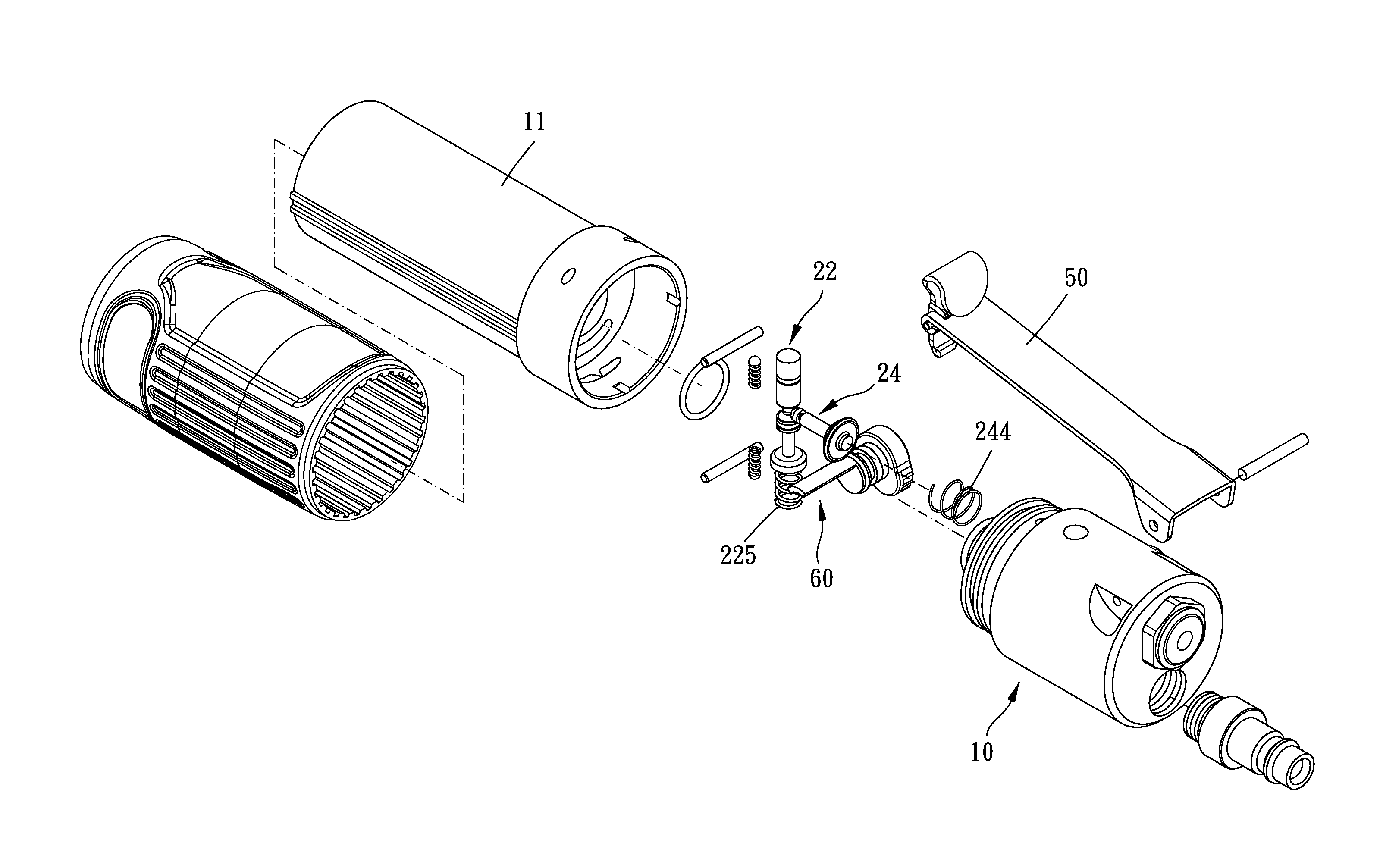
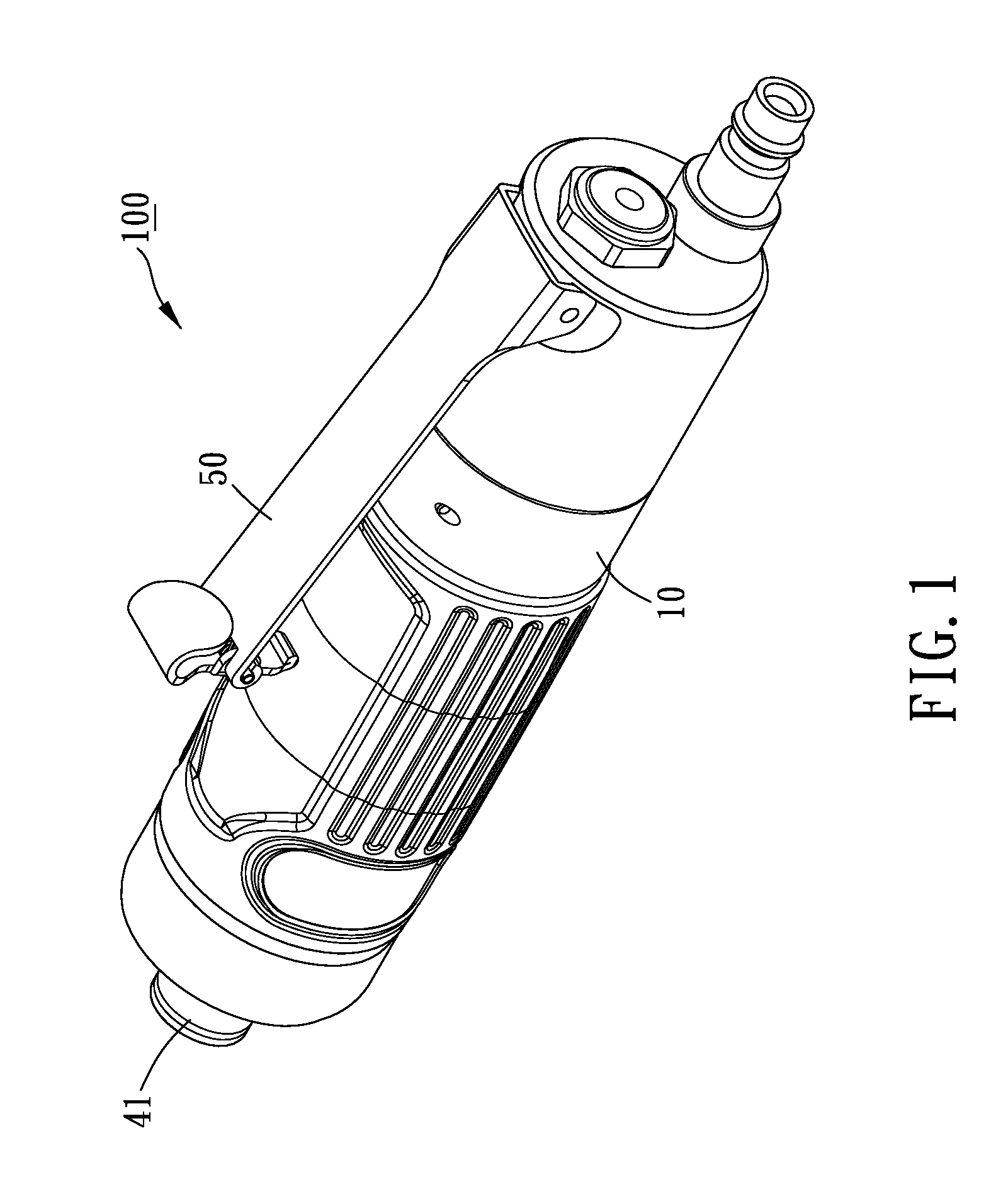
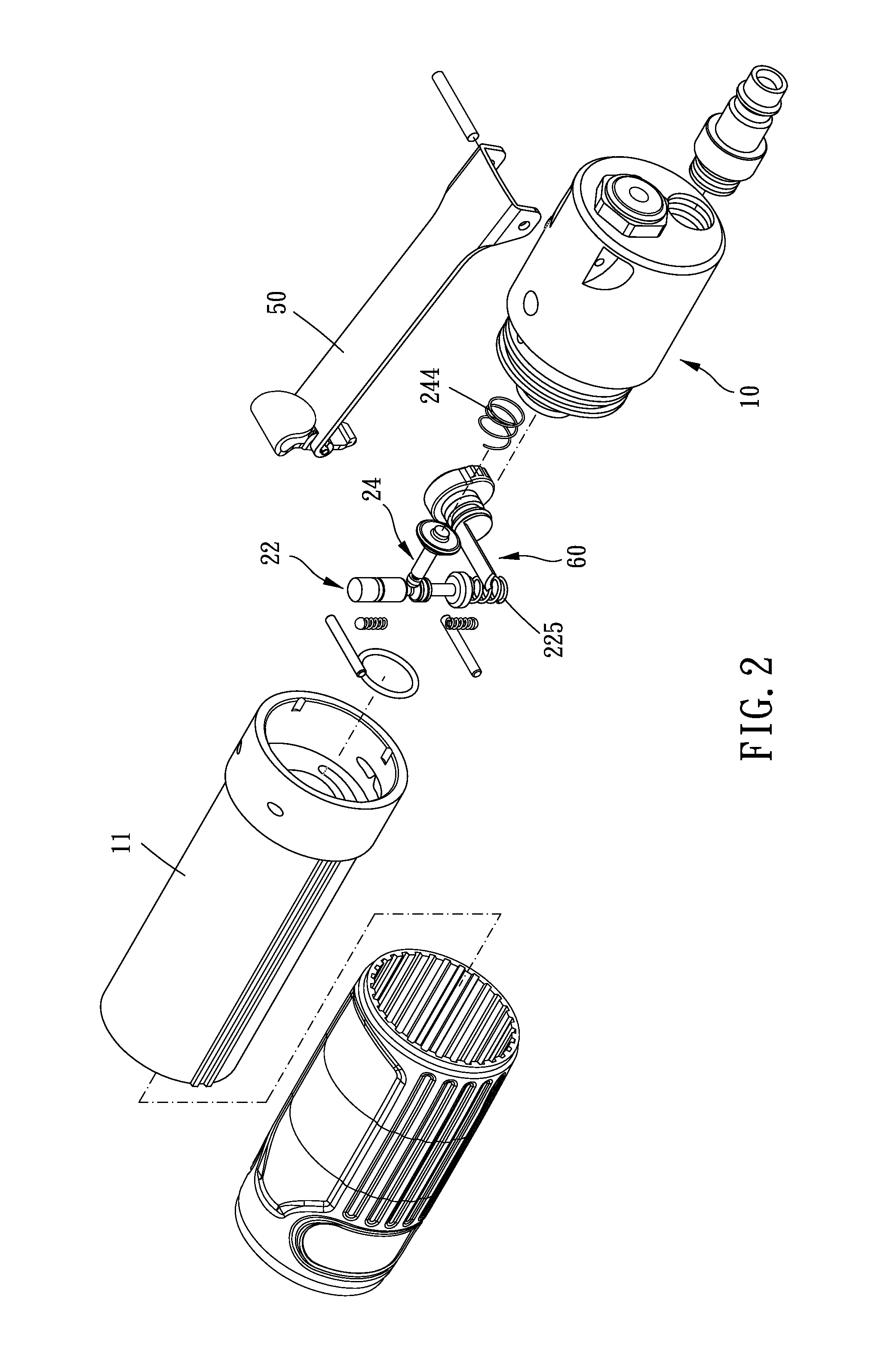
[0028]FIGS. 1 to 5 show a double-valve mechanism 20 (FIG. 5) and a pneumatic tool 100 including the double-valve mechanism 20 according to a first preferred embodiment of the present invention. The pneumatic tool 100 includes a main body 10, a double-valve mechanism 20, a rotor 30 and a tool assembly 40. The pneumatic tool 100 such as, but is not limited to, an air screwdriver, air wrench, air drill, air pull setter, or air sander.

[0029]As shown in FIGS. 3 to 5, the main body 10 includes a cylinder 11, an entrance passage 12, an exhaust passage 13, a...


PUM


Abstract

A double-valve mechanism and a pneumatic tool including the same are provided. The double-valve mechanism is mounted in a main body of the pneumatic tool. The main body has an exhausting passage and an outlet passage communicating therewith, and an entrance passage and an inlet passage communicating therewith. The double-valve mechanism is operable from outside of the main body to move relative to the main body so as to selectively seal an entry of the inlet passage and an exit of the outlet passage. Whereby, the stop of the tool is effectively ensured after the double-valve mechanism is closed, no gas leakage will occurs, the waste of pressurized air energy and defects of the tool will be avoided, and the rotation of the rotor can be quickly stopped.

Description

BACKGROUND OF THE INVENTION[0001]1. Field of the Invention[0002]The present invention relates to a double-valve mechanism, more particularly, to a double-valve mechanism which has entrance and exhaust control vales and a pneumatic tool including the same.[0003]2. Description of the Prior Art[0004]In a conventional pneumatic tool, a pneumatic motor is used to drive a working tool so as to drive a workpiece rotating or proceed machining, processing or the like. An air wrench like a kind of the above conventional pneumatic tool is disclosed in U.S. Pat. No. 5,901,794.[0005]In a conventional pneumatic tool like the kind of the above conventional one, the pneumatic motor is driven by pressurized air, in which the pressurized air enters into the pneumatic tool via an inlet passage to drive the pneumatic motor rotating and then exhausts outside the pneumatic tool via an exhaust passage.[0006]However, the exhaust passage of the conventional pneumatic tool is not sealed; the pneumatic rotor ...

Claims


Application Information

Patent Timeline
IPC IPC(8): B25F5/00F16K11/14
CPCF16K11/14B25F5/00Y10T137/87225
Inventor TING, CHIH-MINGLIN, TIENLAI, PO-JEN
Owner HYPHONE MASCH IND CO LTD
Why Eureka
Try Eureka