LED Light Control and Management System

a technology of management system and led light, applied in the direction of electric variable regulation, process and machine control, instruments, etc., can solve the problems of requiring the vast majority of expense and difficulty, and achieve the effect of reducing peak inrush current, low power communication, and optimal physiological and psychological effects

Active Publication Date: 2014-07-10
FEDERAL LAW ENFORCEMENT DEV SERVICES
View PDF2 Cites 31 Cited by
  • Summary
  • Abstract
  • Description
  • Claims
  • Application Information

AI Technical Summary

Benefits of technology

[0036]In at least one embodiment, the present invention includes the use of visible light as the communications channel between client and host, which offers security, reliability, system testing and configuration, bandwidth, infrastructure, and mobility, among other things. Yet another advantage of the present invention improves security, because light does not go through walls, in contrast to radio communications, and steps can be taken to obstruct visible transmissions with a much greater certainty than with high frequency radio waves.
[0037]In some embodiments, the invention enables individual or selected groups of LED lights to be selectively configured for optimal physiological and psychological effects and benefits for one or more applications. LEDs may be readily reconfigured without changes to physical structures for diverse applications having different requirements for optimal physiological and / or psychological effects and benefits.
[0038]In some embodiments, the present invention has the capacity to provide low power communications for energy management, emergency back-up, security and special applications utilizing alternative power sources such as batteries or solar cells.
[0039]In at least one embodiment, the present invention reduces peak inrush current by controlling the timing of illumination and other equipment start-up.
[0040]In some embodiments, the present invention also has sufficient communications bandwidth to incorporate smart video integration. The present invention also has the ability to provide embedded communications through visible light, whether or not the visible light is at an intensity great enough for sufficient duration to be detected by the human eye.
[0041]These and other embodiments which characterize the invention are pointed out with particularity in the claims annexed hereto and forming a part hereof. However, for further understanding of the invention, its advantages and objectives obtained by its use, reference should be made to the drawings which form a further part hereof and the accompanying descriptive matter, in which there is illustrated and described embodiments of the invention.

Problems solved by technology

Last mile refers to the final portion of any communications system, and it is commonly known that the last mile normally demands the vast majority of expense and difficulty in establishing and maintaining a system.

Method used


Image

  • LED Light Control and Management System
  • LED Light Control and Management System
  • LED Light Control and Management System

Examples


Embodiment Construction

[0065]While this invention may be embodied in many different forms, there are described in detail herein specific alternative embodiments of the invention. This description is an exemplification of the principles of the invention and is not intended to limit the invention to the particular embodiments illustrated. For the purposes of this disclosure, like reference numerals in the figures shall refer to like features unless otherwise indicated.

[0066]In each of the embodiments discussed below, the LEDs may be formed of the same or different colors. The controller may be configured to select the color of the LEDs to be illuminated forming the light signal.

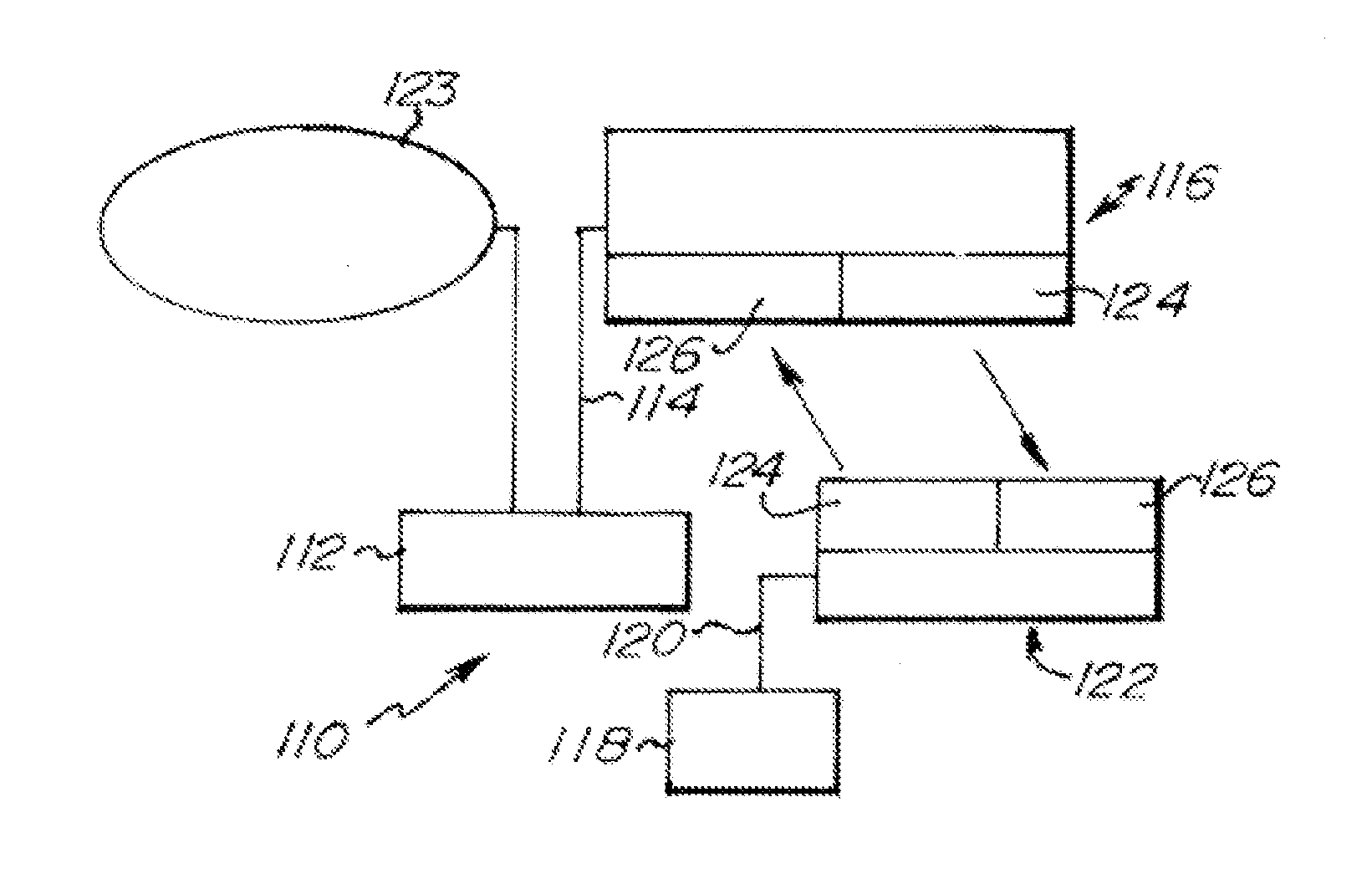
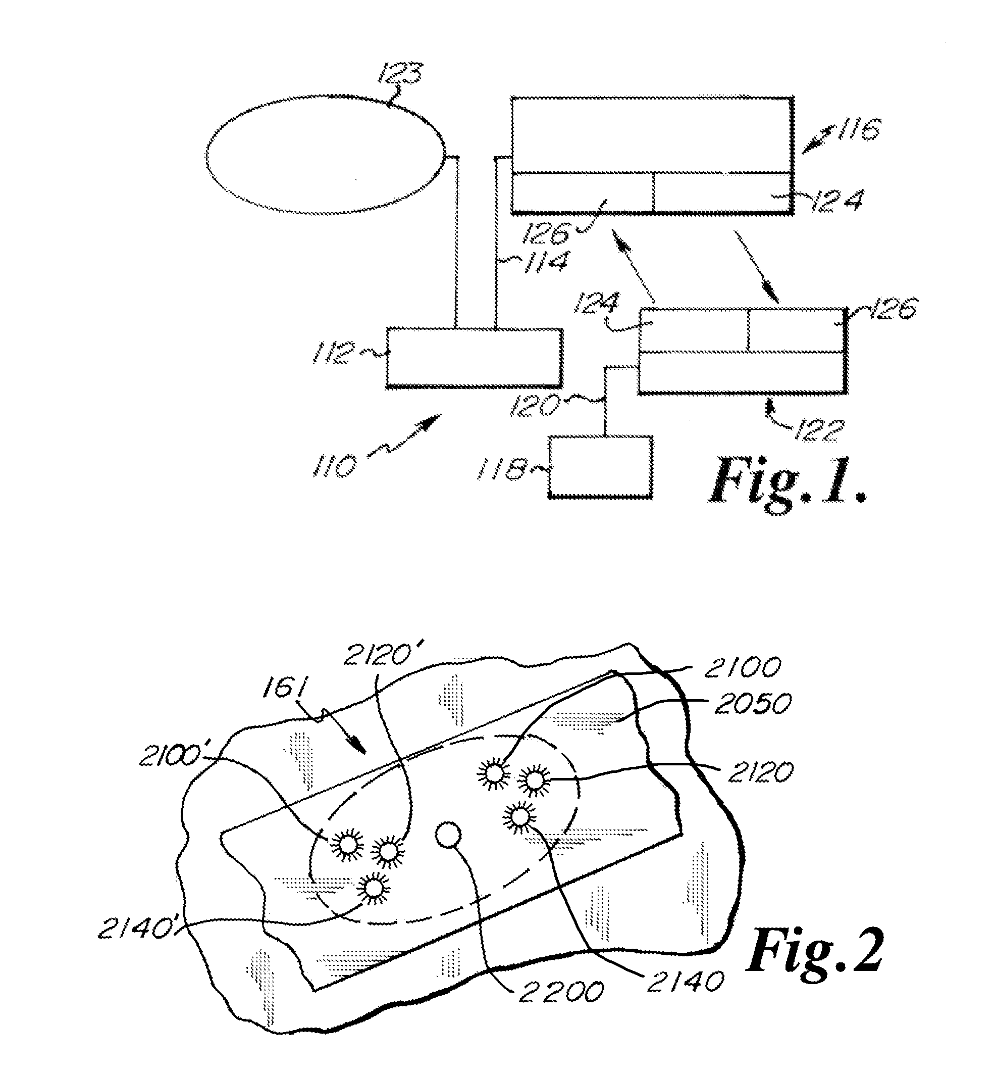
[0067]FIG. 1 depicts an exemplary embodiment 110 of an LED light and communication system. FIG. 1 shows a server PC 112 connected via a USB cable 114 to a server optical transceiver (XCVR) 116, and a client PC 118 connected via a USB cable 120 to a client optical transceiver 122. The server PC 112 is in communication with a network 1...


PUM


Abstract

An LED light and communication system is in communication with a broadband over power line communications system. The LED light and communication system includes at least one optical transceiver light fixture. The optical transceiver light fixture includes a plurality of light emitting diodes, at least one photodetector, and a processor. A facility management unit is in communication with the processor. The facility management unit is constructed and arranged to control the operation of the optical transceiver light fixture.

Description

CROSS-REFERENCE TO RELATED APPLICATIONS[0001]This application claims priority to Provisional Application No. 61 / 778,672, filed Mar. 13, 2013, the disclosure of which is expressly incorporated herein by reference.[0002]This application is a continuation-in-part of U.S. patent application Ser. No. 13 / 427,358 filed on Mar. 22, 2013 which is a continuation of U.S. patent application Ser. No. 12 / 126,342 filed May 23, 2008 now abandoned which claimed priority to U.S. Provisional Patent Application Ser. No. 60 / 931,611 filed May 24, 2007 the disclosures all of which are expressly incorporated by reference herein in their entireties.[0003]This application is a continuation-in-part of U.S. patent application Ser. No. 14 / 050759 filed Oct. 10, 2013 which is a continuation of U.S. patent application Ser. No. 13 / 426,962, now U.S. Pat. No. 8,571,411 filed Mar. 22, 2012 which is a continuation of U.S. patent application Ser. No. 12 / 126,469 filed May 23, 2008 now abandoned which claims priority to P...

Claims


Application Information

Patent Timeline
Patent Type & Authority Applications(United States)
IPC IPC(8): H05B33/08H05B44/00
CPCH05B33/0845H04B10/1143H04B10/1149H04B10/116H05B45/10H05B47/185
Inventor PEDERSON, JOHN C.
Owner FEDERAL LAW ENFORCEMENT DEV SERVICES
Why Eureka
Try Eureka