AI technical title is built by Patsnap AI team. It summarizes the technical point description of the patent document.
a technology of combustion engine and twin turbine, which is applied in the direction of machines/engines, non-positive displacement engines, hot gas positive displacement engine plants, etc., can solve the problems of large system size, large tesla turbine system, and still remain in the prior arts, so as to increase the torque generation, simplify the design and manufacture of tesla turbines, and increase the efficiency of energy transfer
Inactive Publication Date: 2014-07-17
LAM VINH MINH GLISTTENMEER +3
View PDF14 Cites 3 Cited by
Summary
Abstract
Description
Claims
Application Information
AI Technical Summary
This helps you quickly interpret patents by identifying the three key elements:
Problems solved by technology
Method used
Benefits of technology
Benefits of technology
The objective of this invention is to improve the Tesla turbine by incorporating a combustion chamber inside it. This makes the design and manufacturing of the turbine easier and more efficient. The combustion gases are close to the turbine discs, which increases the energy transfer. By making the turbine as simple as possible and allowing it to be coupled with other turbines, the amount of torque generated is increased. The Tesla Twin Turbines Combustion Engine Module is designed to be modular, so multiple modules can be coupled together to create a more powerful engine. This invention provides a more significant improvement in terms of ease of manufacturing, higher efficiency, and smaller compact size compared to prior art.
Problems solved by technology
Despite many improvement over the century, problems still remain in the prior arts.
The prior arts utilize an external combustion source which makes for a very bulky Tesla turbinesystem.
Amero et al design a system where the combustion gases are generated externally, which also lead to a bulky system.
Furthermore, a toroidal combustion chamber surrounding a Tesla turbine is complicated to manufacture and assemble.
Method used
Image
Click on the blue label to locate the original text in one second.
Reading with bidirectional positioning of images and text.
Examples
Embodiment Construction
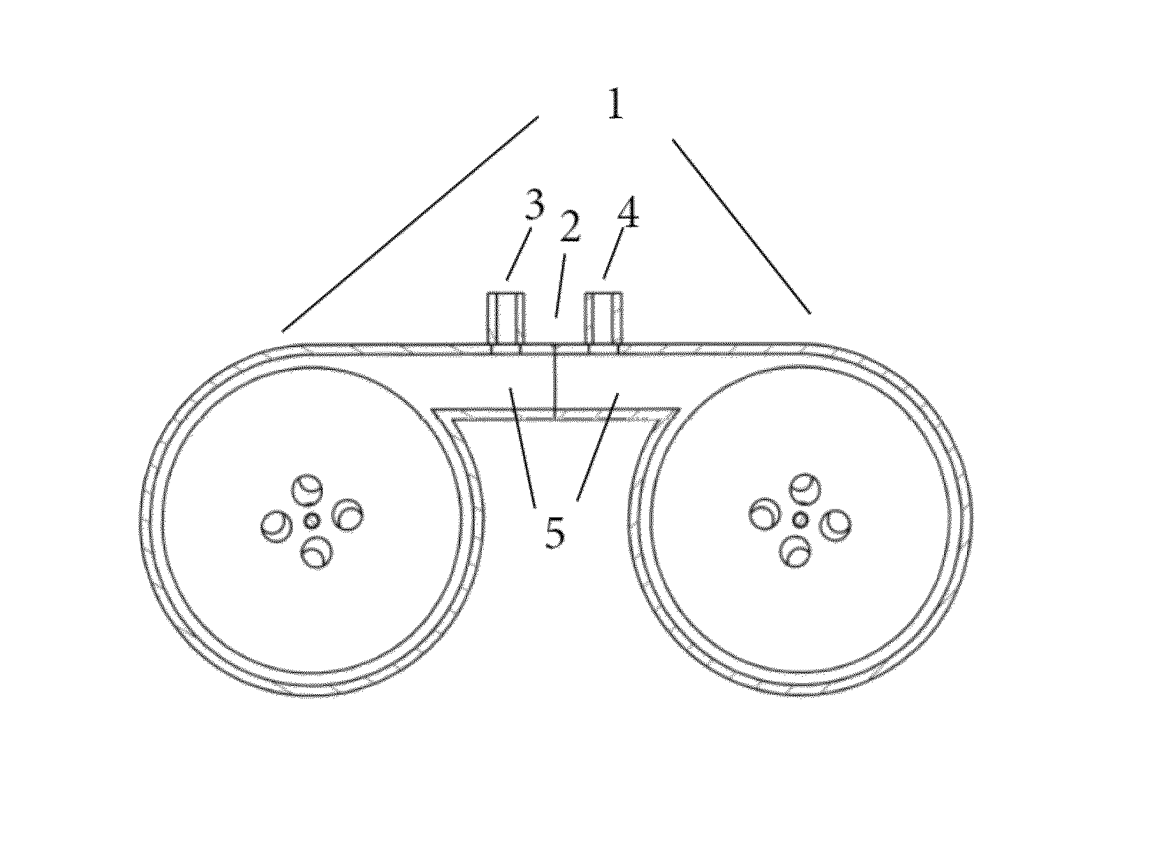
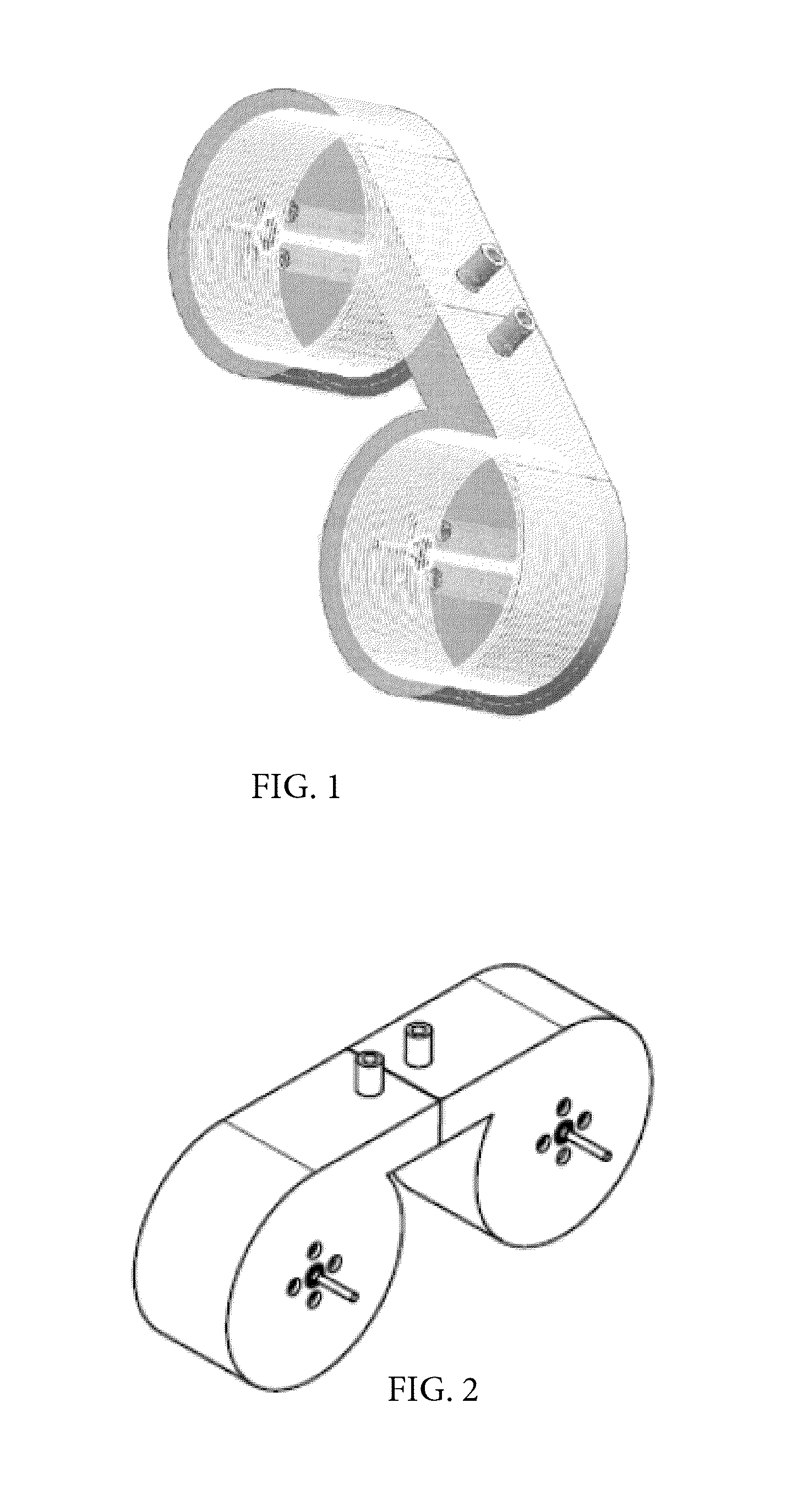
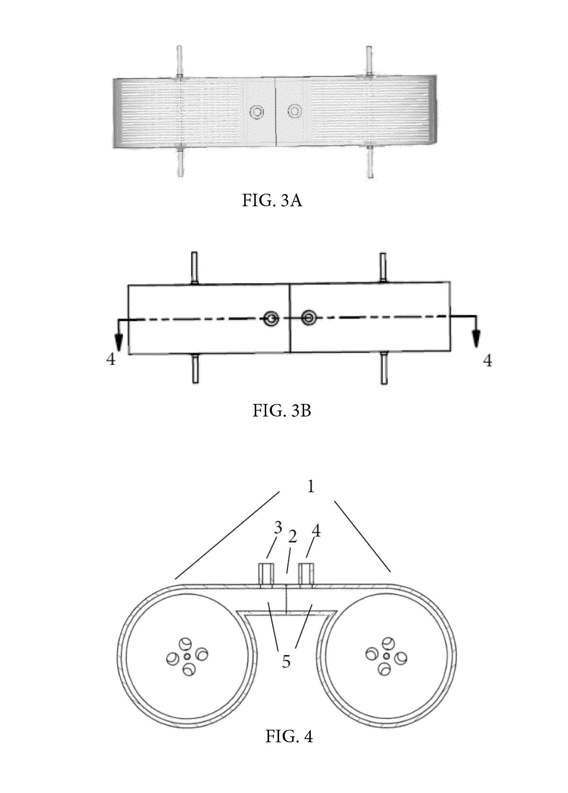
[0019]We will describe in detail our invention, the Tesla Twin Turbines Combustion Engine Module, which will be called the “module” from here on. FIG. 1 shows a shaded transparent isometric view of the module, showing the inner mechanism of our module. FIG. 2 shows another isometric view of the module with the general shape and outer surface clearly depicted. FIG. 3A shows a transparent and shaded top view of the module. In this view, we can also see the inner mechanism of the module. FIG. 3B shows the top view with a view line showing where the cross section will be depicted in FIG. 4. The cross section view in FIG. 4 shows two Tesla turbines 1 being welded along the combustion chamber interface 2. The air-fuel mixture inlet 3 is channeled into the combustion chamber 5. The ignition inlet 4 is also channeled into the combustion chamber 5.
[0020]FIG. 5A shows individually the pair of Tesla turbines. The air-fuel inlet 3 is channeled through the metallic housing 6 which encloses the t...
PUM
Abstract
A new type of engine module is described based on the Tesla turbine. Our Tesla Twin Turbines Combustion Engine Module comprises of two Tesla turbines welded together, forming a combustion chamber in between. The combustion chamber includes an air-fuel mixture inlet and an ignition inlet. Fuel-air mixture is injected through the air-fuel inlet into the combustion chamber which is ignited by an ignition device. The high temperature combustion gas flow in opposite directions across 2 stacks of evenly spaced smooth parallel discs, transferring energy into rotating the discs via the mechanism of boundary layer laminar flow interaction. The pair of rotating stacks of discs rotates a pair of rods. The gas exits through exhaust holes or openings adjacent to the pair of rods. The rotating rods can be used to drive generators or do useful works.
Description
FIELD OF THE INVENTION[0001]The present invention relates to the field of combustion engine constructed from evenly spaced stacks of smooth parallel discs that utilizes the mechanism of laminar boundary layer flow interaction to transfer the energy from the combustion gas to the smooth rotating discs which turn a pair of rotating rods.BACKGROUND OF THE INVENTIONDescription of the Prior Art[0002]References Cited:Patent NumberDateInventorField1,013,248Jan. 2, 1912Wilkinson et al415 / 901,061,206May 6, 1913Tesla415 / 901,061,142May 6, 1913Tesla415 / 90GB186083Mar. 24, 1921Tesla415 / 903,010,281Nov. 28, 1961Ceirenka et al 60 / 39.373,007,311Nov. 7, 1961Amero et al415 / 906,399,020Jun. 4, 2002Lee et al 420 / 5376,503,067Jan. 7, 2003Palumbo415 / 906,779,964Aug. 24, 2004Dial415 / 1 7,241,106Jul. 10, 2007Aviña415 / 90US 2010 / 0107647 A1Oct. 29, 2009Bergen 60 / 7227,632,061Dec. 15, 2009Neeb et al415 / 90[0003]There is a need in our world for a new kind of engine that can utilize clean burning combustible fuel. Mor...
Claims
Application Information
Patent Timeline
Application Date:The date an application was filed.
Publication Date:The date a patent or application was officially published.
First Publication Date:The earliest publication date of a patent with the same application number.
Issue Date:Publication date of the patent grant document.
PCT Entry Date:The Entry date of PCT National Phase.
Estimated Expiry Date:The statutory expiry date of a patent right according to the Patent Law, and it is the longest term of protection that the patent right can achieve without the termination of the patent right due to other reasons(Term extension factor has been taken into account ).
Invalid Date:Actual expiry date is based on effective date or publication date of legal transaction data of invalid patent.
Patent Type & AuthorityApplications(United States)
IPC IPC(8): F02C3/14
CPCF02C3/14F01D1/36
InventorLAM, VINH MINH GLISTTENMEERLAM, ETHANLAM, MEGANLAM, VICTOR

