
Braking mechanism for a roller shade controller, control mechanism comprising same and control handle

a technology of braking mechanism and control handle, which is applied in the direction of curtain accessories, curtain suspension devices, building components, etc., can solve the problems of ineffective arrangement for users requiring precise shade positioning, control devices often operate slowly, and devices often do not offer precise control of shade positioning

Active Publication Date: 2014-07-17
SUNPROJECT CANADA
View PDF13 Cites 1 Cited by
  • Summary
  • Abstract
  • Description
  • Claims
  • Application Information

AI Technical Summary

Benefits of technology

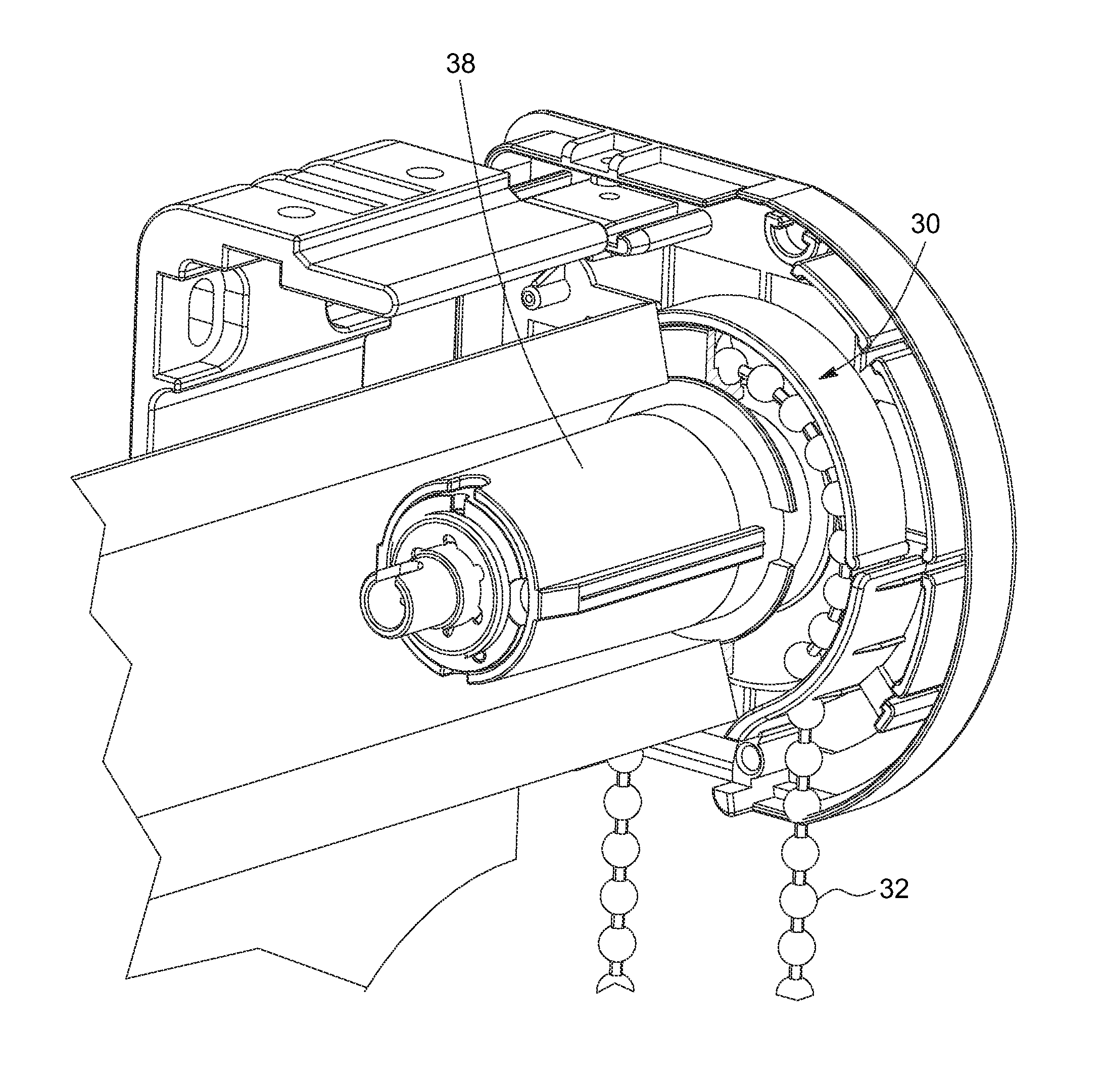
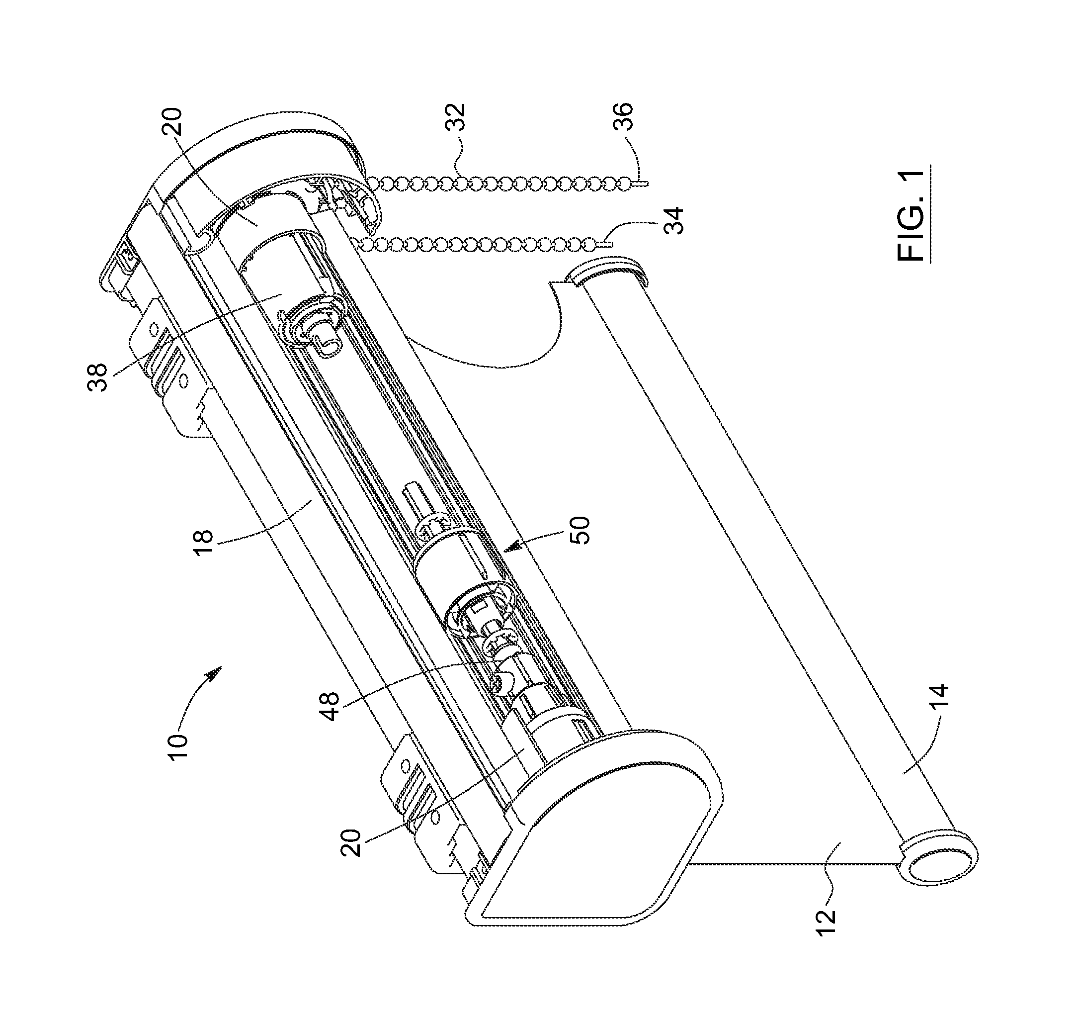
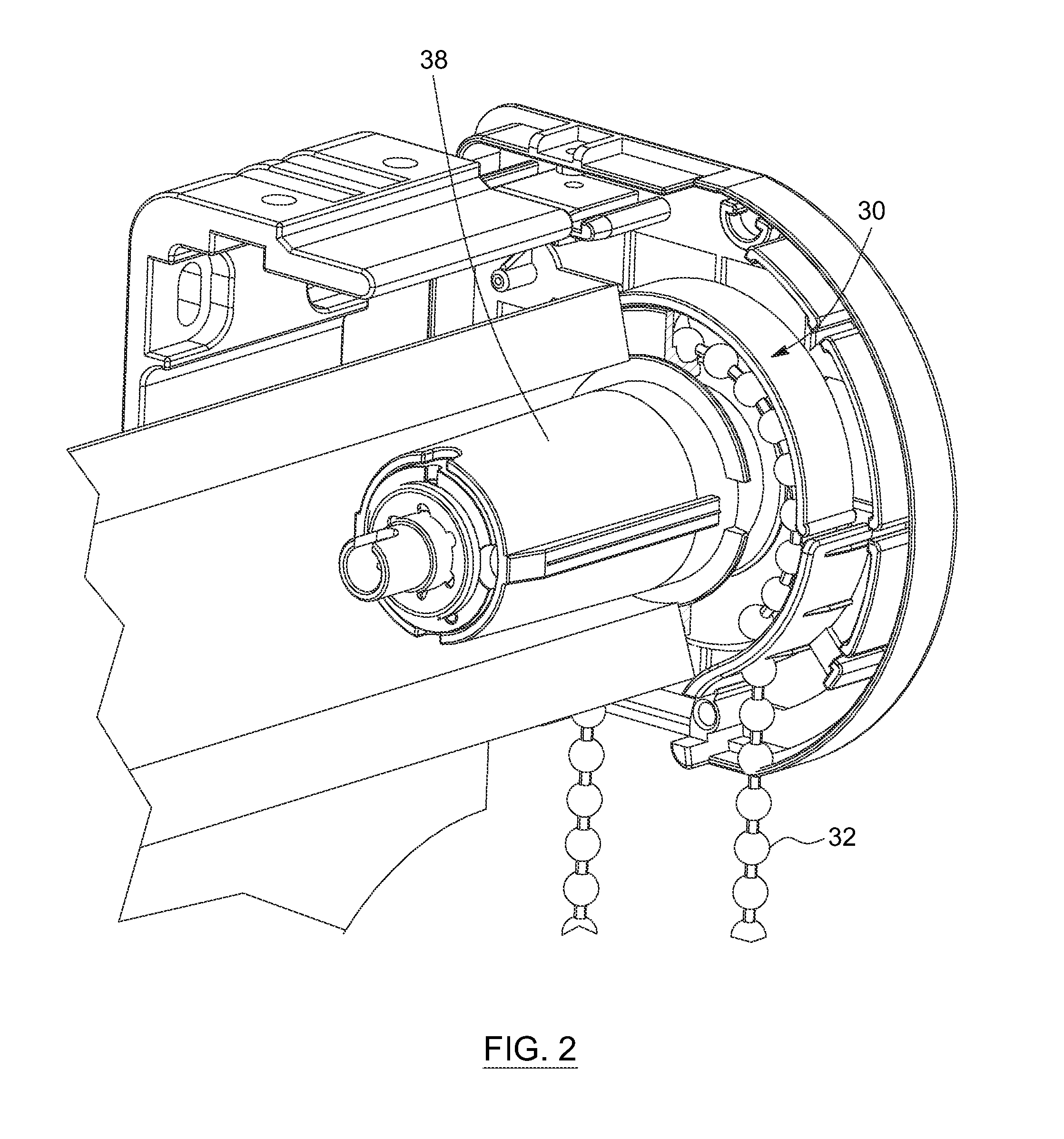
The patent text describes a braking mechanism for a roller shade control system and a control mechanism for a roller shade that includes the braking mechanism. The braking mechanism comprises a stationary member and a rotating member that can rotate in either the winding or unwinding direction. The connecting assembly frictionally engages the rotating member when it is rotated in the unwinding direction and disengages it when it is rotated in the winding direction. The actuation assembly comprises an actuation member and the braking mechanism is operatively connected to it. The braking mechanism is designed to improve the stability and safety of the roller shade control system by preventing accidental movement of the roller shade during wind-up or unwinding. The operating handle for the control mechanism also includes a dampening mechanism to reduce the relative motion between the main body and the actuation member. The technical effects of this patent text are improved safety and stability of the roller shade control system through the use of a braking mechanism and reduced risk of accidental movement of the roller shade through the use of an operating handle with a dampening mechanism.

Problems solved by technology

However, known control devices often do not offer a precise control of the positioning of the shade to the user actuating the controller.
Such an arrangement is ineffective for users requiring precise positioning of the shade, as the additional revolution varies the position of the shade after the user has stopped interacting with the controller.
However, known friction based braking systems are active both when the roller shade is wound and unwound and therefore require an additional displacement force to be applied by the user both when the shade is moved up or down, which can be undesirable.
Moreover, control devices often operate slowly for the winding / unwinding of the window shade.
The slow winding / unwinding of the window shade is particularly disadvantageous for shades having a long length, which are increasingly present in the market.
Consequently, an operator must often pull on an extremity of the activating chain or rope several times before the desired position of the window shade is reached, which can be long and tiresome.
In most cases, the formed loops are long and can be found within the reach of children, which can lead to important security issues.

Method used


Image

  • Braking mechanism for a roller shade controller, control mechanism comprising same and control handle
  • Braking mechanism for a roller shade controller, control mechanism comprising same and control handle
  • Braking mechanism for a roller shade controller, control mechanism comprising same and control handle

Examples


Embodiment Construction

[0025]In the following description, the same numerical references refer to similar elements, The embodiments, geometrical configurations, materials mentioned and / or dimensions shown in the figures or described in the present description are preferred embodiments only, given solely for exemplification purposes.

[0026]Moreover, although the embodiments of the braking mechanism, control mechanism, handle and corresponding parts thereof consist of certain geometrical configurations as explained and illustrated herein, not all of these components and geometries are essential to the invention and thus should not be taken in their restrictive sense. It is to be understood, as also apparent to a person skilled in the art, that other suitable components and cooperation thereinbetween, as well as other suitable geometrical configurations, may be used for the braking mechanism, control mechanism and handle, as will be briefly explained herein and as can be easily inferred herefrom by a person s...


PUM


Abstract

A braking mechanism for a roller shade control system. The braking mechanism includes a stationary member and a rotating member rotatable relative to the stationary member. The rotating member is rotatable in a winding direction or an unwinding direction. The braking mechanism also includes a connecting assembly operatively connecting the stationary member and the rotating member. The connecting assembly frictionally engages the rotating member when the rotating member is rotated in the unwinding direction and is frictionally disengaged from the rotating member when the rotating member is rotated in the winding direction. A control mechanism includes such a braking mechanism and an operating handle for operating the control mechanism.

Description

[0001]This application claims benefit of Ser. No. 611753,647, filed 17 Jan. 2013 in the United States and which application is incorporated herein by reference. To the extent appropriate, a claim of priority is made to each of the above disclosed applications.FIELD OF THE INVENTION[0002]The present invention relates to the field of roller shades controllers. More particularly, it relates to a braking mechanism for a roller shade controller, a control mechanism comprising such a braking mechanism and a control handle for controlling such control mechanism.BACKGROUND[0003]Numerous types of control devices for window roller shades are known in the art for winding and unwinding a roller shade around a tubular core when actuated by a user, and maintaining the shade in a stable desired position when not actuated.[0004]However, known control devices often do not offer a precise control of the positioning of the shade to the user actuating the controller. For example, in many instances, the...

Claims


Application Information

Patent Timeline
Patent Type & Authority Applications(United States)
IPC IPC(8): F16D49/08E06B9/44E06B9/56
CPCF16D49/08E06B9/56E06B9/44E06B9/42E06B9/50E06B9/60E06B9/78E06B9/84E06B9/90E06B2009/785E06B2009/905
Inventor BERGAMASCHI, GIANNI
Owner SUNPROJECT CANADA
Learn More