
Dual-cell mechanical flotation system with intermittent skimming

a mechanical flotation system and mechanical flotation technology, applied in the direction of filtration separation, biological water/sewage treatment, separation process, etc., can solve the problems of inability to dispose, contaminated water is ever present, above-mentioned device suffers from various drawbacks, etc., to reduce power requirements, reduce capital and operating costs, and reduce the effect of footprin

Inactive Publication Date: 2008-08-26
CAMERSON INT CORP
View PDF5 Cites 0 Cited by
  • Summary
  • Abstract
  • Description
  • Claims
  • Application Information

AI Technical Summary

Benefits of technology

[0017]It is another object of the present invention to provide a two-cell, mechanical, cylindrical gas flotation machine having a reduced footprint, reduced power requirements and reduced capital and operating costs that overcomes the adverse wave effects on floating platforms.
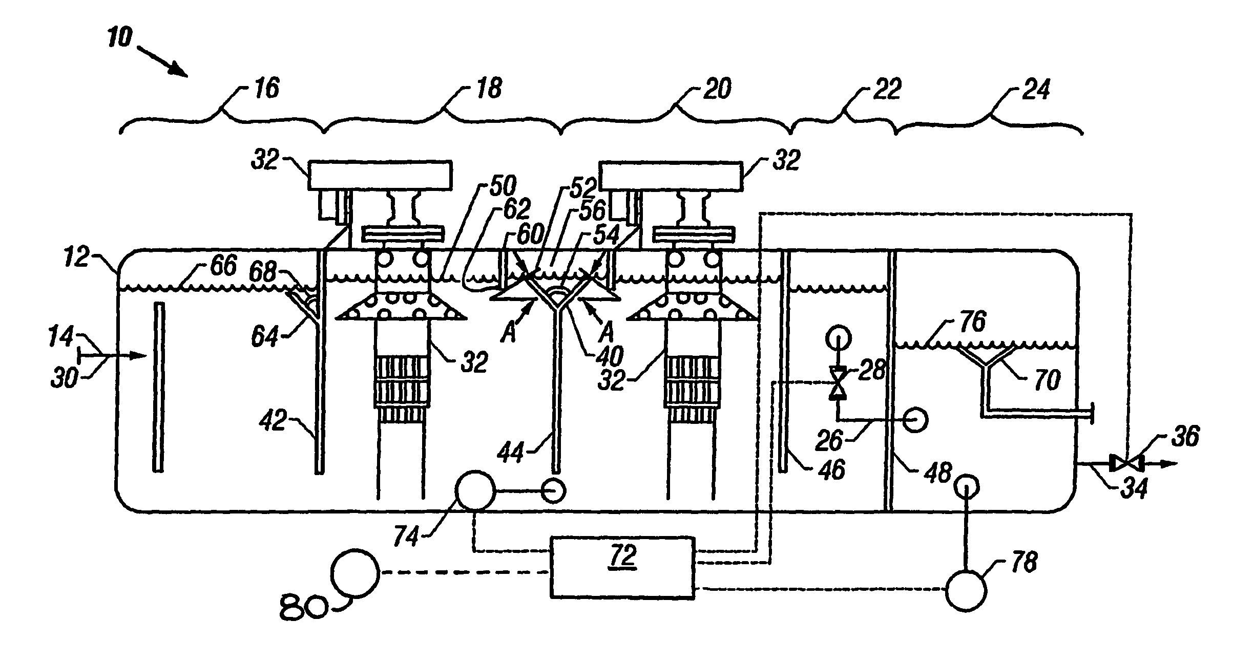
[0018]In carrying out these and other objects of the invention, there is provided, in one form, an apparatus for removing suspended matter from a liquid, which apparatus includes a vessel for receiving a flow of liquid having suspended matter therein. The vessel has a plurality of partitions sequentially dividing the vessel into an inlet chamber, at least a first gasification chamber and a second gasification chamber, and an outlet chamber, where each adjacent chamber fluidly communicates with one another. The vessel also has a discharge chamber having a fluid communication with the outlet chamber. The apparatus includes an inlet to introduce the flow of liquid into the inlet chamber and an outlet for removing clarified liquid from the discharge chamber. The apparatus includes a mechanism for ingesting and mixing gas into the liquid of each gasification chamber for creating a turbulent area and for attracting the suspended matter and for carrying the suspended matter to an upper portion of the vessel. The interface of the gas and liquid is termed a liquid level or froth level. Also included is a primary skim collection channel extending at least partially along the top of the partition between the first gasification chamber and the second gasification chamber for collecting suspended matter in the upper portion of both gasification chambers. A controller is present for regulating the height of the liquid level in response to the movement of the vessel. The liquid level may be lowered during times of pitching and rolling of the vessel (caused by pitching and rolling of the floating offshore hydrocarbon recovery platform) and then raised for collecting suspended matter. Finally the invention optionally includes at least one baffle near the primary skim collection channel to dampen motion of the liquid caused by movement of the vessel.

Problems solved by technology

In many industries, including oil, paper and pulp, textile, electricity generating and food processing, there is an ever-present problem of contaminated water as a by-product of various processes.
As a result, the water becomes contaminated with oil and solids encountered in the formation, and therefore cannot be disposed of simply by dumping it into the surrounding water.
The above-mentioned device suffers from various drawbacks.
Also the rectangular tanks, by virtue of their construction, cannot withstand pressures in excess of 2 oz. per square inch (0.8 kPa) internal.
This is particularly disadvantageous especially where system pressures upstream of the oil / water separator are prevalent or where noxious or lethal gases such as hydrogen sulfide are present.
Furthermore, the rectangular tanks having the skimmers are limited in volumetric capacity because full utilization of the tank is not allowed.
In addition, although these tanks are described as “gas tight”, gas pressures are maintained by continuously venting to the atmosphere, which is a potentially dangerous practice if lethal or flammable gases are present.
This can be disadvantageous when a continuous flow of fluid is desirable.
Furthermore, there is no means for removing contaminants that may accumulate at the top of the inlet chamber, and no means for venting gas, which may have been entrained in the influent, which accumulates in the inlet chamber.
In addition, there is no means for retaining gas in the vessel when the skim outlet valve is opened, creating a potentially dangerous situation if noxious, lethal or flammable gases are present in the tank.
Another problem that is often encountered with the baffles terminating a distance above the tank bottom is that some portion of influent tends to pass under the baffles without being directed to a high turbulence area and contacted by gas bubbles.
Additionally, the velocity of flow in the degasification chamber is relatively high, which leads to insufficient final oil / water separation.

Method used


Image

  • Dual-cell mechanical flotation system with intermittent skimming
  • Dual-cell mechanical flotation system with intermittent skimming

Examples


Embodiment Construction

[0021]The present invention will now be described, by way of example, and not limitation, with the influent being water contaminated with oil and other suspended particulates. It is to be understood that the present invention has utility in numerous applications in which it is desirable to separate suspended matter and / or oil from a liquid, and that the suspended matter, the liquid, or both may be the desired product of the process.

[0022]Referring now to the FIGURE, the system 10 of the apparatus of a preferred embodiment of the invention includes a vessel 12 for receiving a flow of liquid 14 having suspended matter mixed therewith, where the vessel 12 in a preferred embodiment has a continuous cylindrical sidewall and is capable of withstanding substantial internal pressures as may be encountered when processing produced water from an oil well. Vessel 12 is divided into an inlet chamber 16, at least a first gasification chamber 18, a second gasification chamber 20, and an outlet ch...


PUM

PropertyMeasurementUnit
angleaaaaaaaaaa
angleaaaaaaaaaa
angleaaaaaaaaaa

Abstract

It has been discovered that a mechanical flotation system (10) having only two cells (18, 20) can be nearly as efficient as one having more cells, yet provide an apparatus with a considerably smaller footprint, significantly reduced capital and operating costs, as well as be resistant to floating oil recovery platform wave effects. The dual-cell mechanical flotation system (10) has, in sequential order, an inlet chamber (16) and two gasification chambers or cells (18, 20), each with at least one gas ingestion and mixing mechanism (32), and a discharge chamber (24). A common primary skim collection channel (40) atop the partition (44) dividing the gasification chambers (18, 20) efficiently channels away the bulk of the floating collected matter. At least one baffle (60) depending from the top of the vessel (12) near the primary skim collection channel (40) helps dampen the action of the fluid containing the suspended matter when the vessel (12) is affected by wave motion against the floating oil production platform. The liquid or froth levels (50, 66, and 76) can be intermittently raised for collection or otherwise lowered during periods of excessive turbulence (e.g. pitch or roll) to prevent clarified liquid from being collected with suspended matter.

Description

CROSS-REFERENCE TO RELATED APPLICATION[0001]This application is a continuation-in-part of International Application Serial No. PCT / US01 / 18336 filed Jun. 1, 2001.FIELD OF THE INVENTION[0002]The present invention relates to methods and apparatus for removing suspended matter from liquid, and more particularly relates, in one embodiment, to methods and apparatus for separating suspended contaminants and / or oil from water, particularly on an offshore hydrocarbon recovery platform subject to pitch and roll.BACKGROUND OF THE INVENTION[0003]In many industries, including oil, paper and pulp, textile, electricity generating and food processing, there is an ever-present problem of contaminated water as a by-product of various processes. In particular, water is often used to aid in the production of oil and gas on offshore platforms. This water is usually pumped into a formation in order to be able to pump oil out. As a result, the water becomes contaminated with oil and solids encountered in ...

Claims


Application Information

Patent Timeline
Patent Type & Authority Patents(United States)
IPC IPC(8): C02F1/24B01D17/035B01D17/02B01D17/028B01D17/032B01D17/12B03D1/02B03D1/16
CPCB01D17/0205B03D1/1412B03D1/02B03D1/24C02F1/24B01D17/047B03D1/1406B03D1/22B03D1/028B03D1/1462B01D17/0211B01D17/0214C02F1/40C02F2101/32C02F2209/40C02F2209/42
Inventor STACY, MELVINTOLMIE, KENNETH C.CHEN, JAMES C. T.
Owner CAMERSON INT CORP
Learn More