Boom sprayer and boom vibration control device

a technology of vibration control device and boom, which is applied in the direction of shock absorbers, adjusting devices, agricultural machines, etc., to achieve the effect of suppressing the vibration of the boom

Inactive Publication Date: 2014-07-17
KYB CORP
View PDF4 Cites 36 Cited by
  • Summary
  • Abstract
  • Description
  • Claims
  • Application Information

AI Technical Summary

Benefits of technology

[0005]The object of the present invention is to provide a boom sprayer and a boom vibration control device that are capable of suppressing vibration of a boom in the roll direction.
[0006]According to one aspect of the present invention, a boom vibration control device that is configured to suppress vibration of a boom that is cantilever-supported on a working vehicle is provided. The boom vibration control device includes a left-roll-direction biasing unit that biases the boom in a left roll direction with respective to the working vehicle and a right-roll-direction biasing unit that biases the boom in a right roll direction with respective to the working vehicle. The boom is held at a roll angle at which a biasing force of the left-roll-direction biasing unit and a biasing force of the right-roll-direction biasing unit are balanced.

Problems solved by technology

In this case, the hydraulic cylinder whose extension and contraction is controlled by the control device cannot absorb the high-frequency vibration input to the booms from the vehicle body of the working vehicle, and there is a possibility that the booms periodically repeat rolling movement in the roll direction is caused.

Method used


Image

  • Boom sprayer and boom vibration control device
  • Boom sprayer and boom vibration control device
  • Boom sprayer and boom vibration control device

Examples


first embodiment

[0016]First, the first embodiment will be described.

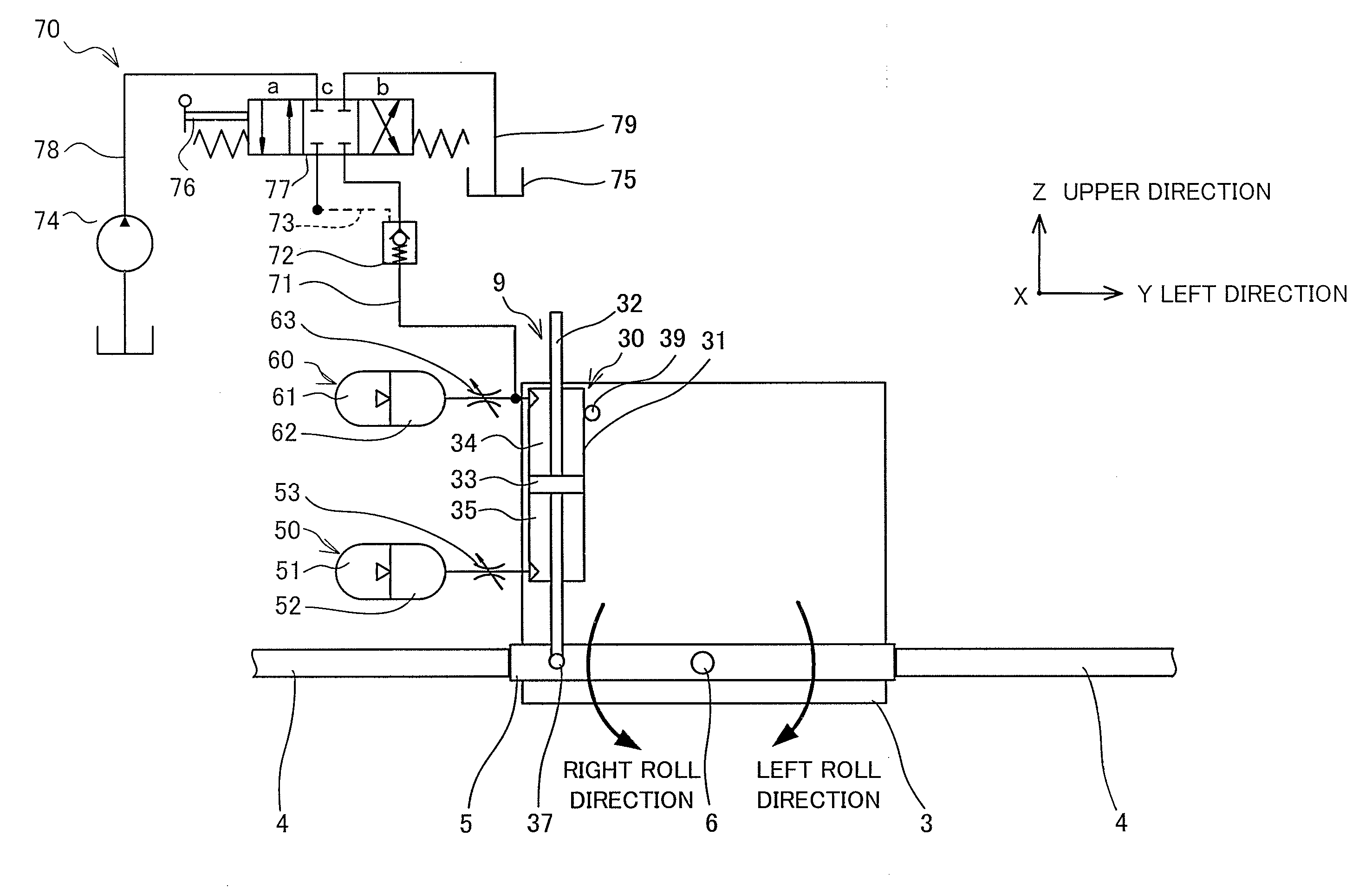
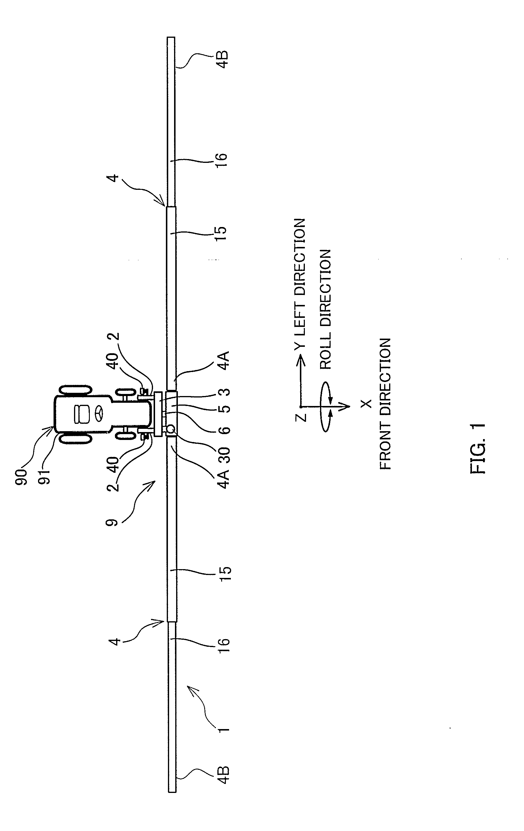
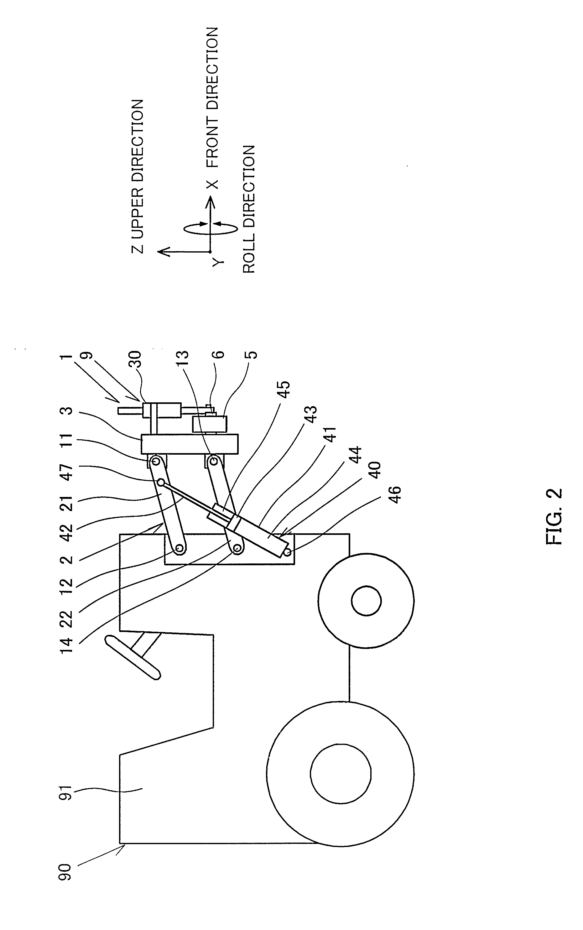
[0017]A boom sprayer 1 shown in FIG. 1 is an agricultural working machine that is mounted on the front side of a working vehicle (tractor) 90 that runs in a field and that sprays pest control fluid (agricultural chemicals) from the working vehicle 90.

[0018]The boom sprayer 1 includes a pair of booms 4 that extend in the left and right directions from the working vehicle 90. The booms 4 include nozzles (not shown) for spraying pest control fluid. During the operation of the boom sprayer 1, a pest control fluid is sprayed from the nozzles of the booms 4 while the working vehicle 90 is running in a field.

[0019]The boom sprayer 1 includes linkage arms 2 that are attached to a vehicle body 91, a raising and lowering mount 3 that is supported on the vehicle body 91 with the linkage arms 2 so as to be able to be raised and lowered, a roll mount 5 that is supported on the raising and lowering mount 3 so as to be rotatable in the roll direc...

second embodiment

[0067]Next, the second embodiment will be described.

[0068]FIG. 5 is a schematic configuration diagram of a boom vibration control device 109 in this embodiment. In the following description, differences from the first embodiment will be mainly described, while structures that are identical to those in the boom sprayer 1 in the first embodiment are assigned the same reference signs, and a description thereof is omitted.

[0069]While the hydraulic-fluid supply and discharge device 70 in the first embodiment includes the manually-switched direction selector valve77, a hydraulic-fluid supply and discharge device 170 in this embodiment includes an electromagnetically-switched direction selector valve 177.

[0070]The boom vibration control device 109 includes a roll angle detector 104 that detects the roll angle of the booms 4 relative to the horizontal line, a set-roll-angle command unit 103 that gives a command for the set roll angle of the booms 4, and a controller 102 that controls the op...

third embodiment

[0075]Next, the third embodiment will be described.

[0076]FIG. 6 is a schematic configuration diagram of a boom vibration control device 209 in this embodiment. In the following description, differences from the first embodiment will be mainly described, while structures that are identical to those in the boom sprayer 1 in the first embodiment are assigned the same reference signs, and a description thereof is omitted.

[0077]While the boom vibration control device 9 in the first embodiment biases the booms 4 in the left and right roll directions by using single fluid pressure cylinder 30, the boom vibration control device 209 in this embodiment biases the booms 4 in the left and right roll directions by using two fluid pressure cylinders 240 and 230.

[0078]The first fluid pressure cylinder 240 includes a first cylinder tube 241 filled with the hydraulic oil and a first piston rod 242 that is slidably inserted into the first cylinder tube 241. The first cylinder tube 241 is rotatably li...


PUM


Abstract

A boom vibration control device that is configured to suppress vibration of a boom that is cantilever-supported on a working vehicle includes a left-roll-direction biasing unit that biases the boom in the left roll direction with respective to the working vehicle and right-roll-direction biasing unit that biases the boom in the right roll direction with respective to the working vehicle. The boom is held at the roll angle at which the biasing force of the left-roll-direction biasing unit and the biasing force of the right-roll-direction biasing unit are balanced.

Description

TECHNICAL FIELD[0001]The present invention relates to a boom sprayer and a boom vibration control device.BACKGROUND ART[0002]JP2004-254526A discloses a boom sprayer. This boom sprayer includes a boom support frame that is raised and lowered by a raising and lowering linkage mechanism provided on a front side of a working vehicle, a rocking shaft that is provided on the boom support frame and extends in the front-to-rear direction, left and right booms that are cantilever-supported on the rocking shaft in a rollable manner, a hydraulic cylinder that is interposed between the boom support frame and the boom, a tilt detector that detects the tilt angle of the working vehicle, a rocking-angle detector that detects the boom-rocking angle against the boom support frame, and a control device that controls the extension and contraction of the hydraulic cylinder.[0003]When the boom sprayer is operated, in the case where the working vehicle is tilted in a roll direction, the booms supported o...

Claims


Application Information

Patent Timeline
Patent Type & Authority Applications(United States)
IPC IPC(8): F16F15/023A01B63/10F16F15/027B05B1/20A01M7/00
CPCF16F15/023A01B63/1006F16F15/027B05B1/20A01M7/0057B05B13/005A01C23/008
Inventor ITO, TATSUOINADA, TAKANORIYOSHIDA, TAKANOBUMIZUKAMI, TOMOMICHIOOTA, ATSUSHISHIBASAKI, DAIKIAKASHI, MASAKITANAKA, YASUO
Owner KYB CORP
Why Eureka
Try Eureka