
Laser pulse energy control systems and methods

a laser pulse and energy control technology, applied in the direction of metal-working equipment, welding equipment, manufacturing tools, etc., can solve the problems of mechanically adjusted polarization optics, variation in laser delivery, and slow speed

Active Publication Date: 2014-07-17
ELECTRO SCI IND INC
View PDF7 Cites 33 Cited by
  • Summary
  • Abstract
  • Description
  • Claims
  • Application Information

AI Technical Summary

Benefits of technology

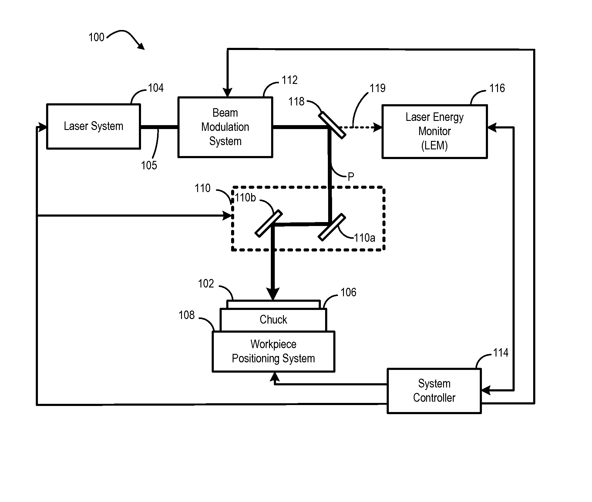
This patent describes a laser system that can control the energy of each laser pulse in a beam of pulses. The system uses a feedback mechanism to adjust the pulse energy based on the energy of previous pulses. This technology allows for more precise control and adjustment of laser power, which can improve the accuracy and efficiency of laser processing.

Problems solved by technology

These conventional approaches have disadvantages including slow speed (e.g., for mechanically-adjusted polarization optics), variation in laser delivery (e.g., in the control of lasing medium pumping or Q-switch timing), or a lack of coordination with other operations of the laser processing apparatus.

Method used


Image

  • Laser pulse energy control systems and methods
  • Laser pulse energy control systems and methods
  • Laser pulse energy control systems and methods

Examples


Embodiment Construction

[0019]Example embodiments are described below with reference to the accompanying drawings. Many different forms and embodiments are possible without deviating from the spirit and teachings of the invention and so the disclosure should not be construed as limited to the example embodiments set forth herein. Rather, these example embodiments are provided so that this disclosure will be thorough and complete, and will convey the scope of the invention to those skilled in the art. In the drawings, the sizes and relative sizes of components may be exaggerated for clarity. The terminology used herein is for the purpose of describing particular example embodiments only and is not intended to be limiting. As used herein, the singular forms “a,”“an” and “the” are intended to include the plural forms as well, unless the context clearly indicates otherwise. It will be further understood that the terms “comprises” and / or “comprising,” when used in this specification, specify the presence of sta...


PUM

PropertyMeasurementUnit
Transmissionaaaaaaaaaa
Energyaaaaaaaaaa
Noiseaaaaaaaaaa

Abstract

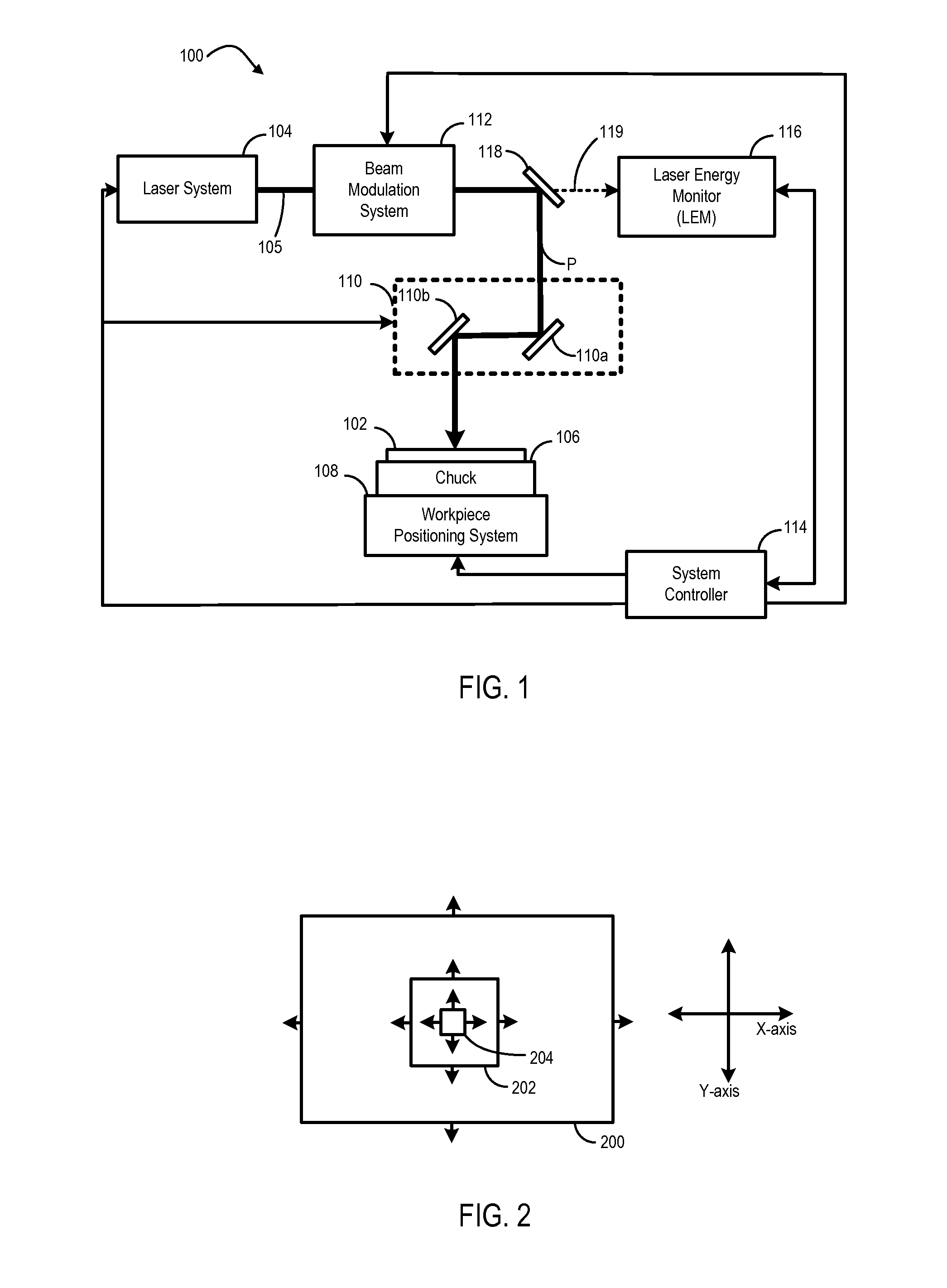
Systems and methods provide laser pulse energy control and / or monitoring. An example laser processing apparatus includes a laser system to generate a beam of laser pulses and a pulse energy control system to adjust the pulse energy of each laser pulse in the beam on a pulse-by-pulse basis. The pulse energy control system includes an open loop feedforward control path that selects a pulse energy transmission value for each laser pulse based on a calibrated transmission curve that maps laser pulse energy as a function of pulse repetition frequency. A laser energy monitor measures the laser pulse energy of each laser pulse in the beam of laser pulses. A power control loop may further adjust the pulse energy of one or more laser pulses in the beam of laser pulses based on feedback from the laser energy monitor.

Description

RELATED APPLICATION[0001]This application claims the benefit under 35 U.S.C. §119(e) of U.S. Provisional Application No. 61 / 751,810, filed Jan. 11, 2013, which is hereby incorporated by reference herein in its entirety.TECHNICAL FIELD[0002]This disclosure relates generally to laser processing apparatuses and to methods of processing workpieces using the same.BACKGROUND INFORMATION[0003]Laser-processing of features (e.g., through-vias, blind vias, trenches, routs, kerfs, and other features) within one or more materials of a workpiece can be sensitive to laser power. In many applications (e.g., in which features are laser-processed by delivering laser pulses onto the workpiece), the speed or efficiency with which a feature is formed, and the quality of the feature ultimately formed, can be very sensitive to the pulse energy of the individual pulses delivered to the workpiece. For example, when laser-processing a workpiece such as a printed circuit board, a flexible printed circuit, or...

Claims


Application Information

Patent Timeline
IPC IPC(8): B23K26/06
CPCB23K26/0626B23K26/03B23K26/10B23K26/082
Inventor UNRATH, MARK A.
Owner ELECTRO SCI IND INC
Learn More