Optical apparatus, light sensitive device with micro-lens and manufacturing method thereof

a technology of light-sensitive devices and optical apparatuses, which is applied in the direction of optical radiation measurement, instruments, and reradiation, can solve the problems of ineffective reduction of the total cost of the optical apparatus b>100/b>, and achieve the effect of reducing the manufacturing cost facilitating the fabrication of the optical apparatus, and reducing the total size of the optical apparatus

Active Publication Date: 2014-07-17
PIXART IMAGING INC
View PDF8 Cites 16 Cited by
  • Summary
  • Abstract
  • Description
  • Claims
  • Application Information

AI Technical Summary

Benefits of technology

[0007]The present disclosure provides an optical apparatus having the advantages of compact, low cost and easy fabrication.
[0008]The present disclosure further provides a light sensitive device with micro-lens and a manufacturing method thereof that may be adapted to the above optical apparatus and has the same advantages.
[0015]As mentioned above, the optical apparatus of the present disclosure may include corresponded micro-lenses disposed above the light sensitive device so as to prevent the use of the conventional single lens such that the fabrication of the optical apparatus is easier and the total size of the optical apparatus is reduced thereby effectively reducing the manufacturing cost of the optical apparatus. Furthermore, in the optical apparatus of the present disclosure a light blocking stack layer is stacked around adjacent photosensitive units so as to limit the incident angle of reflected light beams impinging on every photosensitive unit so as to achieve the function of identifying the object movement and reduce interferences of stray light or light leakage, wherein each of the photosensitive units may include one or a plurality of photodiodes.

Problems solved by technology

Generally speaking, it is possible to reduce the total thickness by adopting the Fresnel lens, but the total cost of the optical apparatus 100 can not be effectively reduced.

Method used


Image

  • Optical apparatus, light sensitive device with micro-lens and manufacturing method thereof
  • Optical apparatus, light sensitive device with micro-lens and manufacturing method thereof
  • Optical apparatus, light sensitive device with micro-lens and manufacturing method thereof

Examples


Embodiment Construction

[0026]The above or other technical contents, characteristics and effects according to the present disclosure will become more apparent from the following detailed description of a preferred embodiment in conjunction with the accompanying drawings. It is to be understood that terms of direction used herein, such as upward, downward, leftward, rightward, forward and backward, are only used for reference but not used to limit the present disclosure.

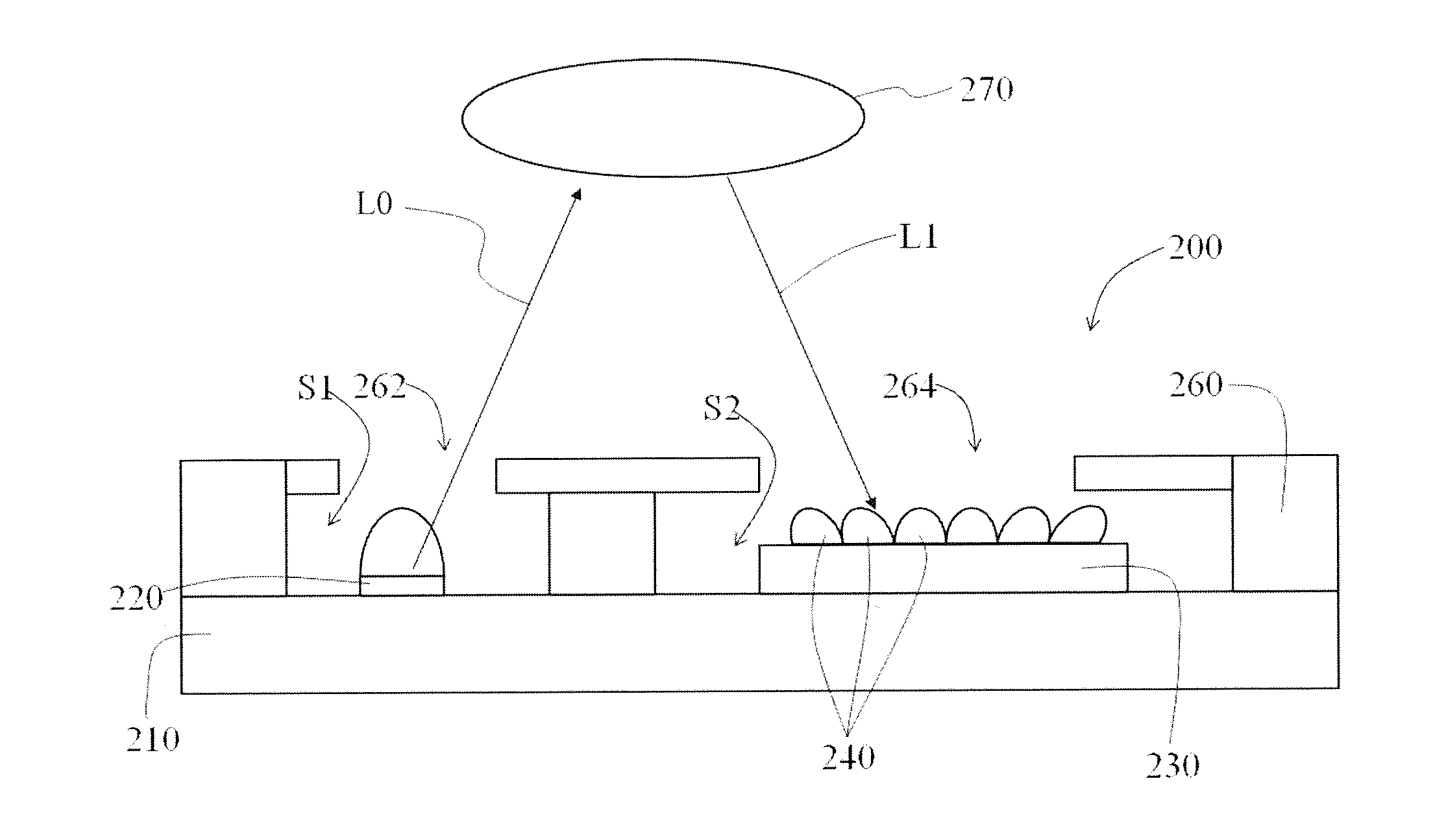
[0027]FIG. 2A shows a cross-section view of the optical apparatus according to an embodiment of the present disclosure and FIGS. 2B and 2C show partial enlarged diagrams of the optical apparatus of FIG. 2A. Referring to FIGS. 2A, 2B and 2C together, the optical apparatus 200 of this embodiment includes a substrate 210, a light emitting device 220, a light sensitive device 230 and a plurality of micro-lenses 240, wherein the optical apparatus 200 is configured to detect an object 270. The light emitting device 220 and the light sensitive devi...


PUM


Abstract

There is provided an optical apparatus including a substrate, a light emitting device, a light sensitive device and a plurality of micro-lenses. The light emitting device is disposed on the substrate and adapted to provide a light beam. The light sensitive device is disposed on the substrate and adapted to receive a light beam reflected from an object, wherein the light sensitive device has a plurality of photosensitive units arranged in matrix. The micro-lenses are disposed above the light sensitive device and respectively opposite to the associated photosensitive units. There is further provided a light sensitive device with micro-lens and a manufacturing method thereof.

Description

CROSS REFERENCE TO RELATED APPLICATION[0001]This application claims the priority benefit of Taiwan Patent Application Serial Number 102101275, filed on Jan. 11, 2013 and Taiwan Patent Application Serial Number 102118898, filed on May 28, 2013, the full disclosure of which are incorporated herein by reference.BACKGROUND[0002]1. Field of the Disclosure[0003]This disclosure generally relates to an optical apparatus and, more particularly, to an optical apparatus having the advantages of compact, low cost and easy fabrication.[0004]2. Description of the Related Art[0005]FIG. 1A show a schematic diagram of sensing the gesture movement by the conventional optical apparatus and FIG. 1B shows a cross-sectional view of the optical apparatus 100 of FIG. 1A. Please referring to FIGS. 1A and 1B together, the optical apparatus 100 includes a package housing 110, a light emitting device 120, a light sensitive device 130 and a condensing lens 140. The package housing 110 has a light outlet 112 and...

Claims


Application Information

Patent Timeline
Patent Type & Authority Applications(United States)
IPC IPC(8): G01S17/02H01L31/0232H01L31/18G01S17/04
CPCG01S17/026H01L31/18H01L31/02325G01S7/4813G01S17/04
Inventor HSU, EN-FENGLIU, CHIA-YUCHEN, CHING-WEI
Owner PIXART IMAGING INC
Why Eureka
Try Eureka