Current-diverting guide plate for probe module and probe module using the same

a technology of current-diverting guide plate and probe module, which is applied in the direction of electrical testing, measurement devices, instruments, etc., can solve the problems of /b>, delay in testing schedule, and easy burnout of probes

Active Publication Date: 2014-07-17
MPI CORP
View PDF4 Cites 31 Cited by
  • Summary
  • Abstract
  • Description
  • Claims
  • Application Information

AI Technical Summary

Benefits of technology

[0008]It is one objective of the present invention to provide a current-diverting guide plate for a probe module, which enables an electric current flowing through probes of the probe module to be diverted effectively.
[0012]Preferably, the conducting layer may be, but not limited to, a composite conducting layer composed of a metal base layer and a metal coating coated on a surface of the metal base layer and containing polymer particles for reducing friction between the through hole and the probe.
[0013]By the above-mentioned technical features of the present invention, the current-diverting guide plate of the present invention thus configured can provide a current-diverting path for the electric current flowing through the probes, thereby preventing the probes from damage caused by an excessive instantaneous current.

Problems solved by technology

However, once the probe diameter is reduced, the probe 13, especially the buckling body 136 of the probe 13, may easily burn out due to an unexpected excessive instantaneous current running therethrough.
If this happens, the damaged probe 13 has to be repaired or exchanged, causing a delay in the testing schedule.

Method used


Image

  • Current-diverting guide plate for probe module and probe module using the same
  • Current-diverting guide plate for probe module and probe module using the same
  • Current-diverting guide plate for probe module and probe module using the same

Examples


Embodiment Construction

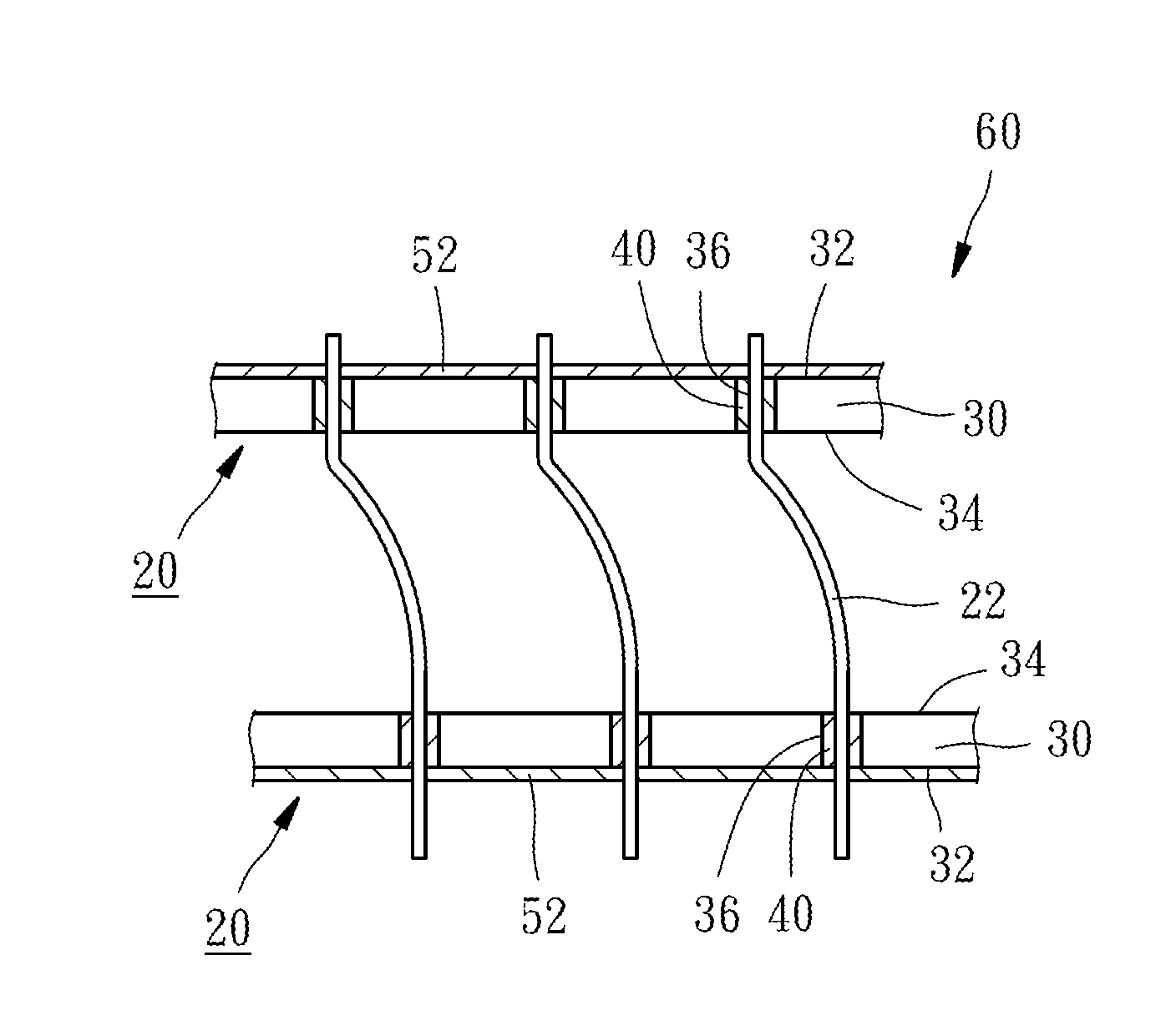
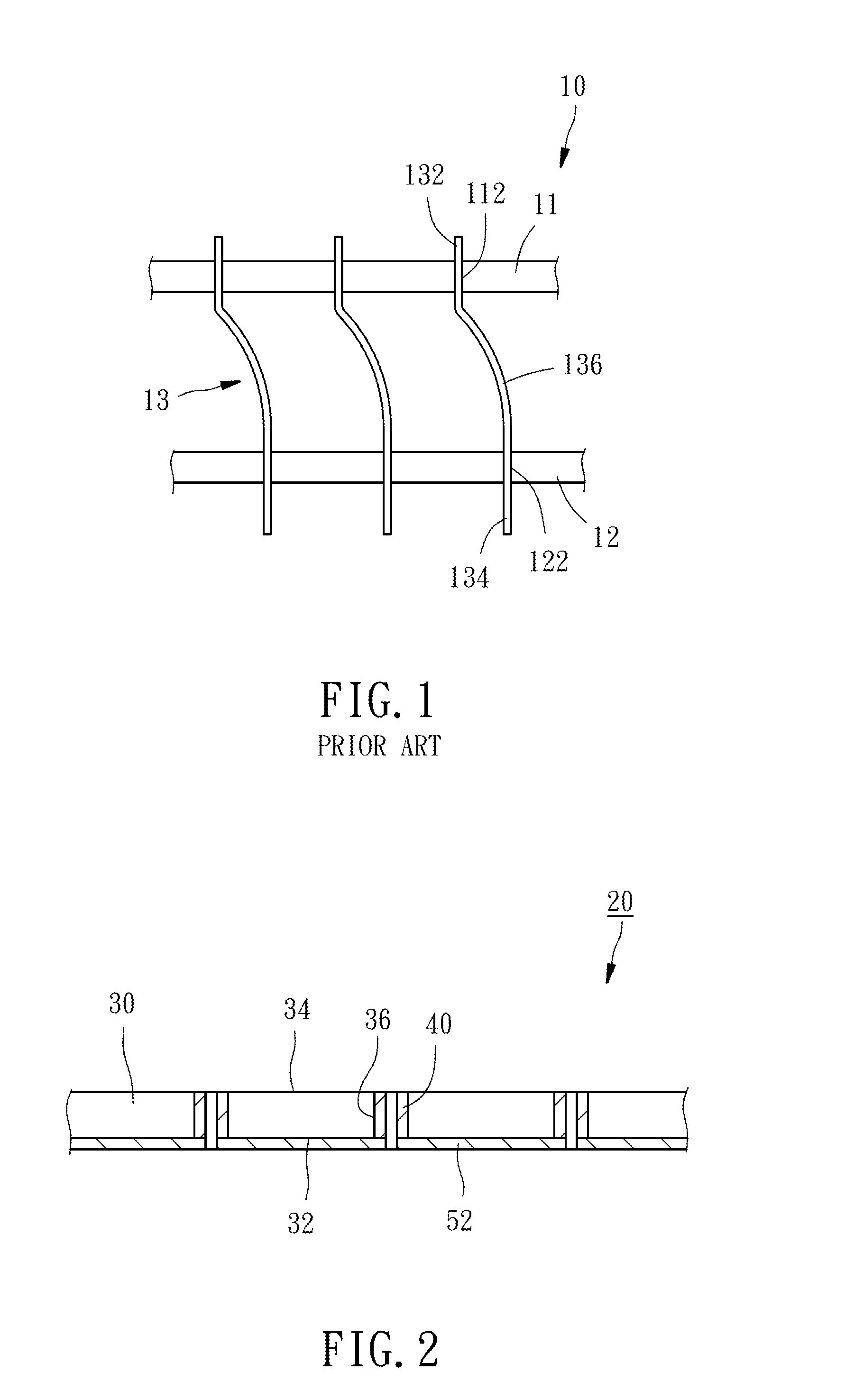
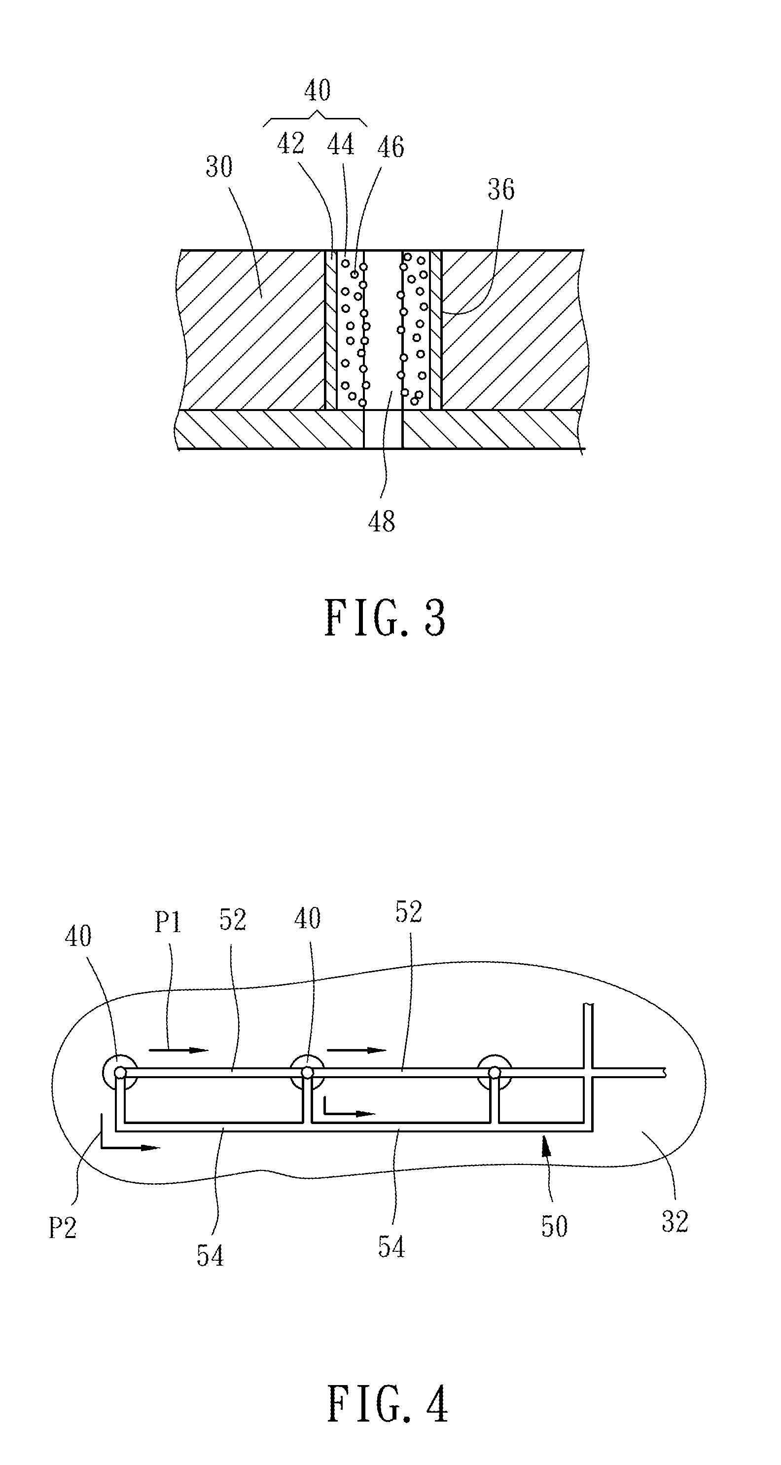
[0024]As shown in FIGS. 2 and 4, a current-diverting guide plate 20 provided according to an embodiment of the present invention comprises a plate body 30, a plurality of composite conducting layers 40, and a current-diverting circuit trace 50. The structural feature of the current-diverting guide plate 20 and the relationship among the elements of the current-diverting guide plate 20 will be detailed described hereinafter.

[0025]The plate body 30 has a first surface 32, a second surface 34 opposite to the first surface 32, and a plurality of through holes 36 penetrating through the first and second surfaces 32, 34 and each having a circular or square cross-sectional shape. In this invention, the through hole 36 has a circular cross section. It is to be understood that the plate body 30 may be made from insulated materials, such as ceramic materials, semiconductor materials or conductor materials, such as silicon-based materials. If the plate body 30 is made from the semiconductor ma...


PUM


Abstract

A current-diverting guide plate for use in a probe module is disclosed to include a plate body having a first surface, a second surface opposite to the first surface, and a plurality of through holes penetrating through the first and second surfaces. A conducting layer is provided at a periphery wall of each through hole of the plate body and electrically coupled to a probe slidably inserted through the through holes. A current-diverting circuit trace is disposed on the first surface of the plate body and electrically connected with the conducting layers for diverting the electric current flowing through probes. Thus, the current-diverting guide plate can be used to prevent the probes from possible damage due to an excessive instantaneous current.

Description

CROSS-REFERENCE TO RELATED APPLICATIONS[0001]This application claims priorities from Taiwan Patent Application No. 102101176 filed on Jan. 11 2013 and Taiwan Patent Application No. 102113494 filed on Apr. 16, 2013, the entire contents of which are incorporated herein by reference.BACKGROUND OF THE INVENTION[0002]1. Field of the Invention[0003]The present invention relates generally to a probe module for a vertical probe card and more particularly, to a guide plate for aligning, guiding and supporting probes, which is provided with a current-diverting path to the probes, and a probe module using the guide plate.[0004]2. Description of the Related Art[0005]FIG. 1 schematically shows a conventional probe module 10 for use in a vertical probe card, comprising an upper guide plate 11, namely an upper die, a lower guide plate 12, namely a lower die, and a plurality of probes 13. The probes 13 each have a head 132 inserted through one of upper guide holes 112 provided at the upper guide pl...

Claims


Application Information

Patent Timeline
Patent Type & Authority Applications(United States)
IPC IPC(8): G01R1/073
CPCG01R1/07307G01R1/36G01R1/067G01R1/06711G01R1/07357
Inventor HSU, HSIEN-TAFAN, HORNG-KUANG
Owner MPI CORP
Why Eureka
Try Eureka