Antenna structure

a technology of antennas and antennas, applied in the direction of antennas, antenna details, electrically short antennas, etc., can solve the problem that the product cannot pass the fcc sar test, and achieve the effect of reducing the radiation of the antenna and reducing the harm to the human body

Inactive Publication Date: 2014-07-17
AUDEN TECHNO
View PDF4 Cites 5 Cited by
  • Summary
  • Abstract
  • Description
  • Claims
  • Application Information

AI Technical Summary

Benefits of technology

[0007]In order to solve the above-mentioned problems, an object of the present invention is to provide an antenna structure, wherein the direction of the rear end or the open end of the radiator of the antenna structure is chan

Problems solved by technology

Therefore, the product c

Method used


Image

  • Antenna structure
  • Antenna structure
  • Antenna structure

Examples


Embodiment Construction

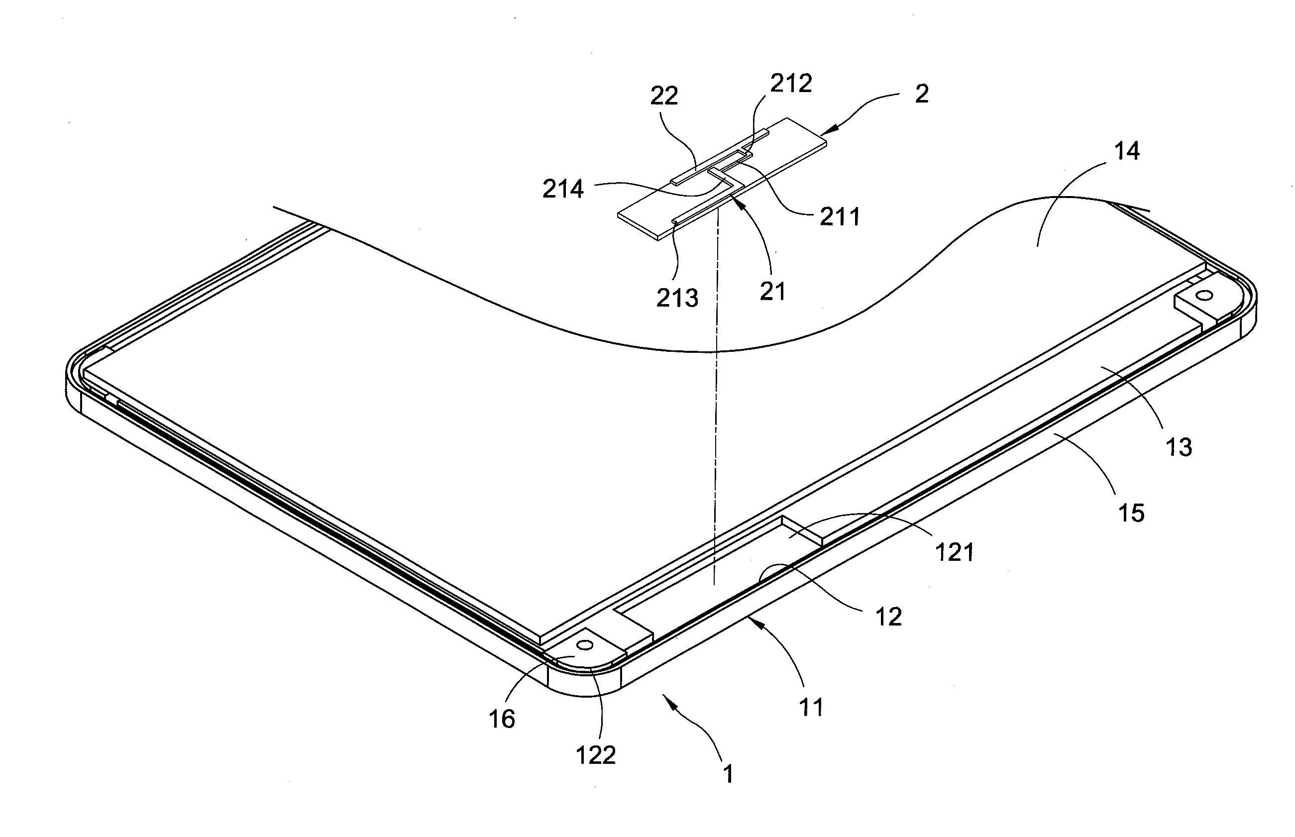
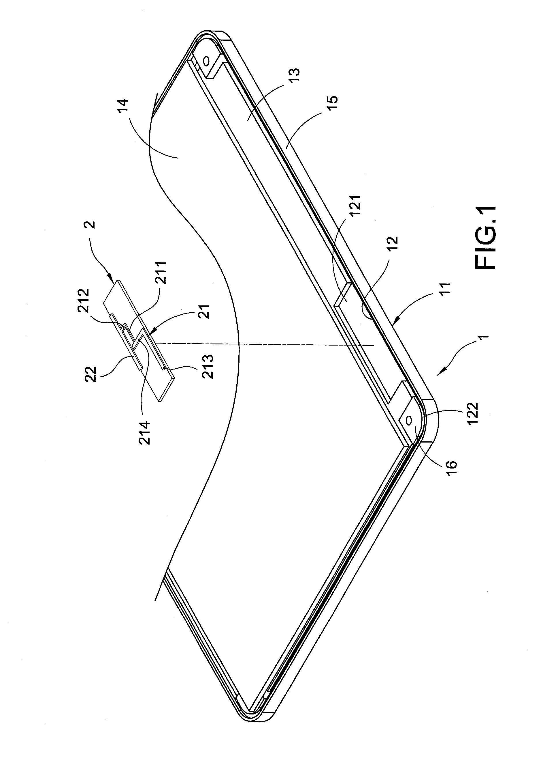
[0015]FIG. 1 shows a diagram of the combination of the antenna and the portable electronic apparatus of the present invention. The antenna structure of the present invention includes a portable electronic apparatus 1 and an antenna 2.

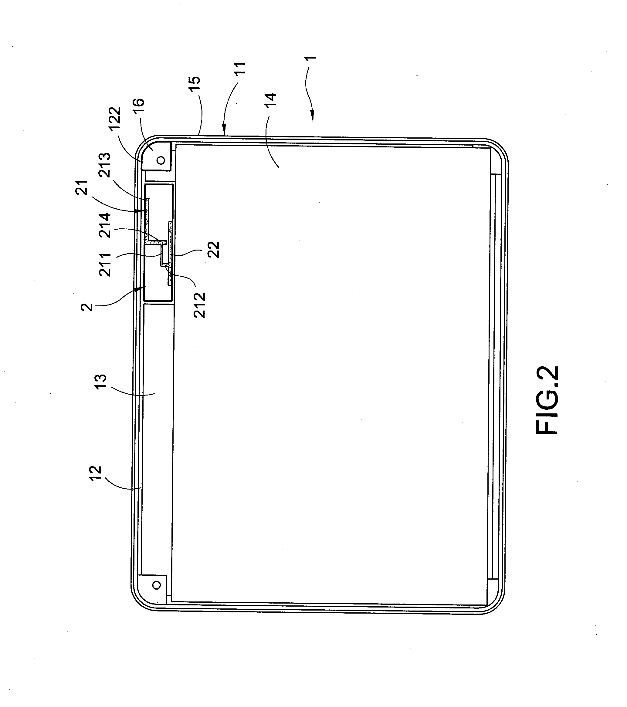
[0016]The portable electronic apparatus 1 includes a housing 11. The housing 11 includes an accommodating space 12. Related parts (such as a printed circuit board 13, a liquid crystal display panel 14, and a camera lens not shown in FIG. 1, and so on) of the portable electronic apparatus 1 are arranged in the accommodating space 12. An installation area 121 is formed between the printed circuit board 13, the liquid crystal display panel 14, and an edge part 15 of the housing 11 after the printed circuit board 13 and the liquid crystal display panel 14 are arranged and stacked in the accommodating space 12. Moreover, the accommodating space 12 includes four corners 122. A metal block 16 is arranged at each corner 122, or the metal block 16 is at the corn...


PUM


Abstract

An antenna structure includes a portable electronic apparatus and an antenna. The portable electronic apparatus includes a housing. At least a metal block is arranged at a corner of the housing. The antenna is arranged in an accommodating space of the housing. The antenna includes a radiator. The radiator includes a rear end and a signal feed-in contact. A distance between the rear end, the signal feed-in contact, and the metal block is about one-fourth wavelength of communication signals, wherein the rear end faces the metal block. Therefore, the SAR of the antenna is reduced.

Description

BACKGROUND OF THE INVENTION[0001]1. Field of the Invention[0002]The present invention relates to an antenna structure, and especially relates to an antenna structure with low electromagnetic wave energy specific absorption rate (SAR).[0003]2. Description of the Related Art[0004]The technology is progressing every day. Therefore, many portable electronic apparatuses, such as Tablet PCs, are invented. The Tablet PCs are slim, light, portable and are used widely.[0005]A product is tested severely before being purchased. The testing items usually include the falling test, the vibration test, the high / low temperature operation test, the EMI / EMC test, and so on. In the falling test, the product is fallen for 26 points, lines and planes. The weakest parts of the product are the corners of the housing of the product. Therefore, in order to pass the falling test more easily, the metal blocks or objects are usually arranged inside the corners of the housing of the product.[0006]However, the s...

Claims


Application Information

Patent Timeline
IPC IPC(8): H01Q1/24
CPCH01Q1/243H01Q1/245H01Q9/0421
Inventor YANG, CHENG-MINLAI, SHIH-CHI
Owner AUDEN TECHNO
Why Eureka
Try Eureka