Unlock instant, AI-driven research and patent intelligence for your innovation.

Light source apparatus and projector

Inactive Publication Date: 2014-07-17
MITSUBISHI ELECTRIC CORP
View PDF7 Cites 10 Cited by
  • Summary
  • Abstract
  • Description
  • Claims
  • Application Information

AI Technical Summary

Benefits of technology

The present invention is about a device called a phosphor wheel that emits light to create an excitation light source with a specific color. The phosphor wheel has a part that scatters and reflects light. The device also includes a rotation driver, a light source that emits the excitation light, a light source that emits light of a different color, a light source optical system to combine the two colors, and a controller that synchronizes the light emissions with the position of the phosphor wheel. This invention helps to stabilize the brightness of the image projected onto a screen.

Problems solved by technology

As a result, there is a problem in that a luminance of the light source utilizing the fluorescent light is changed and a brightness of a image to be projected onto a screen is thus influenced (a brightness of the image is changed).

Method used


Image

  • Light source apparatus and projector
  • Light source apparatus and projector
  • Light source apparatus and projector

Examples


first preferred embodiment

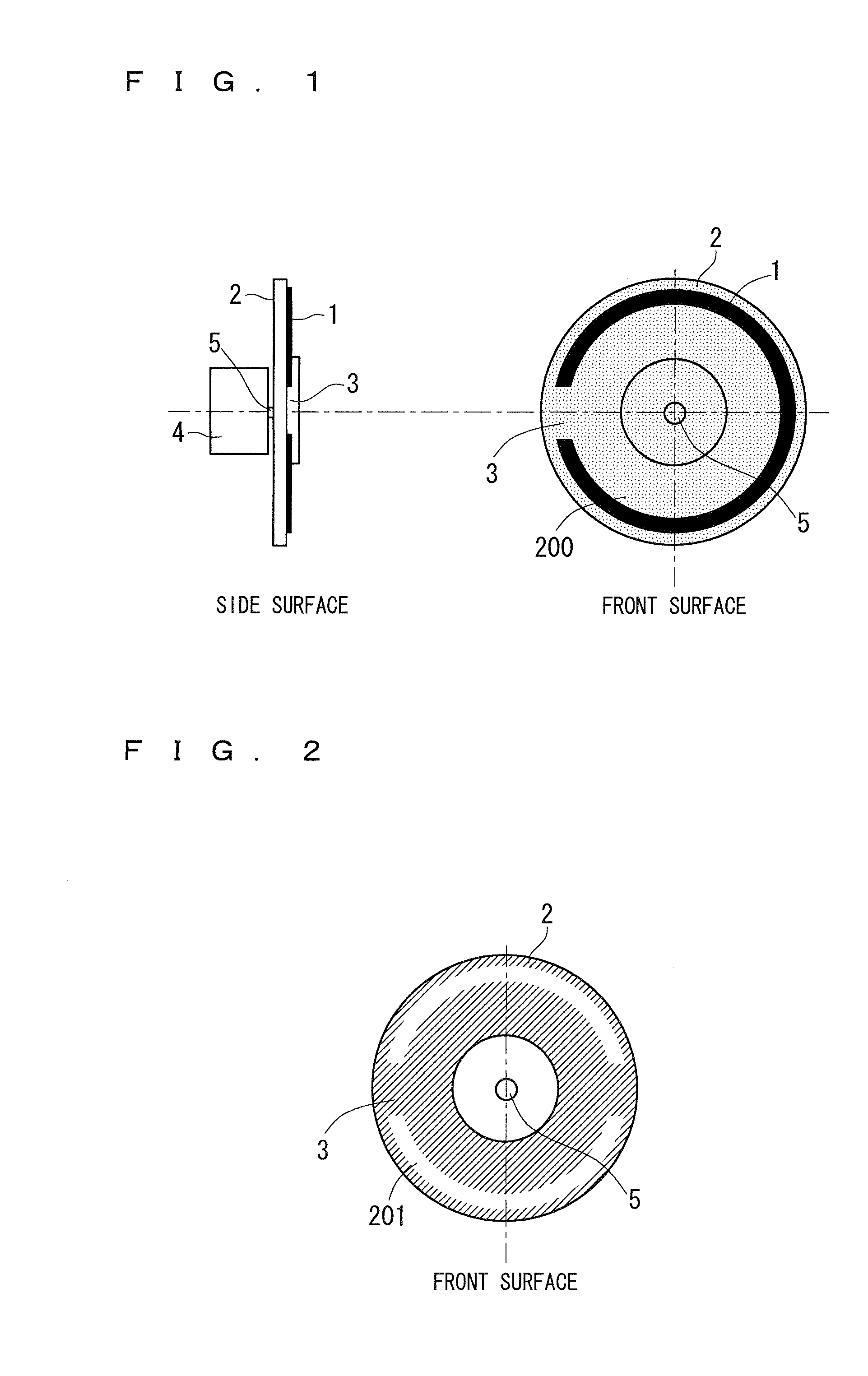
[0022]FIG. 1 shows front and side views of a phosphor wheel unit provided in a light source apparatus of a projector according to a first preferred embodiment of the present invention.

[0023]As shown in FIG. 1, the phosphor wheel unit according to the first preferred embodiment includes a phosphor wheel 2, a wheel motor 4 (a rotation driver) that rotatively drives the phosphor wheel 2, and a rotary drive shaft 5 for coupling the phosphor wheel 2 to the wheel motor 4.

[0024]The phosphor wheel 2 has a disk-shaped metallic base material. The metallic base material has a phosphor 1 disposed in an annular shape. The phosphor 1 has a property for emitting fluorescent light in a green wavelength bandwidth when the metallic base material is irradiated with excitation light in a blue wavelength bandwidth. In other words, the phosphor wheel 2 has the phosphor 1 disposed in the annular shape. The phosphor 1 serves to emit the fluorescent light from the excitation light to the disk-shaped base ma...

second preferred embodiment

[0041]FIG. 5 shows front and side views of a phosphor wheel unit provided in a light source apparatus of a projector according to a second preferred embodiment of the present invention.

[0042]As shown in FIG. 5, in a phosphor wheel 40 according to the second preferred embodiment, a discontinuous portion 41 for diffusing and reflecting light is provided in a phosphor 42 disposed on a disk-shaped metallic base material of the phosphor wheel 40. Moreover, the phosphor 42 has the discontinuous portion 41 in a part thereof in the same manner as in the first preferred embodiment. However, the metallic base material has a mirror surface provided on a whole surface thereof, and a portion corresponding to a ground of the phosphor 42 neither diffuses nor reflects the light.

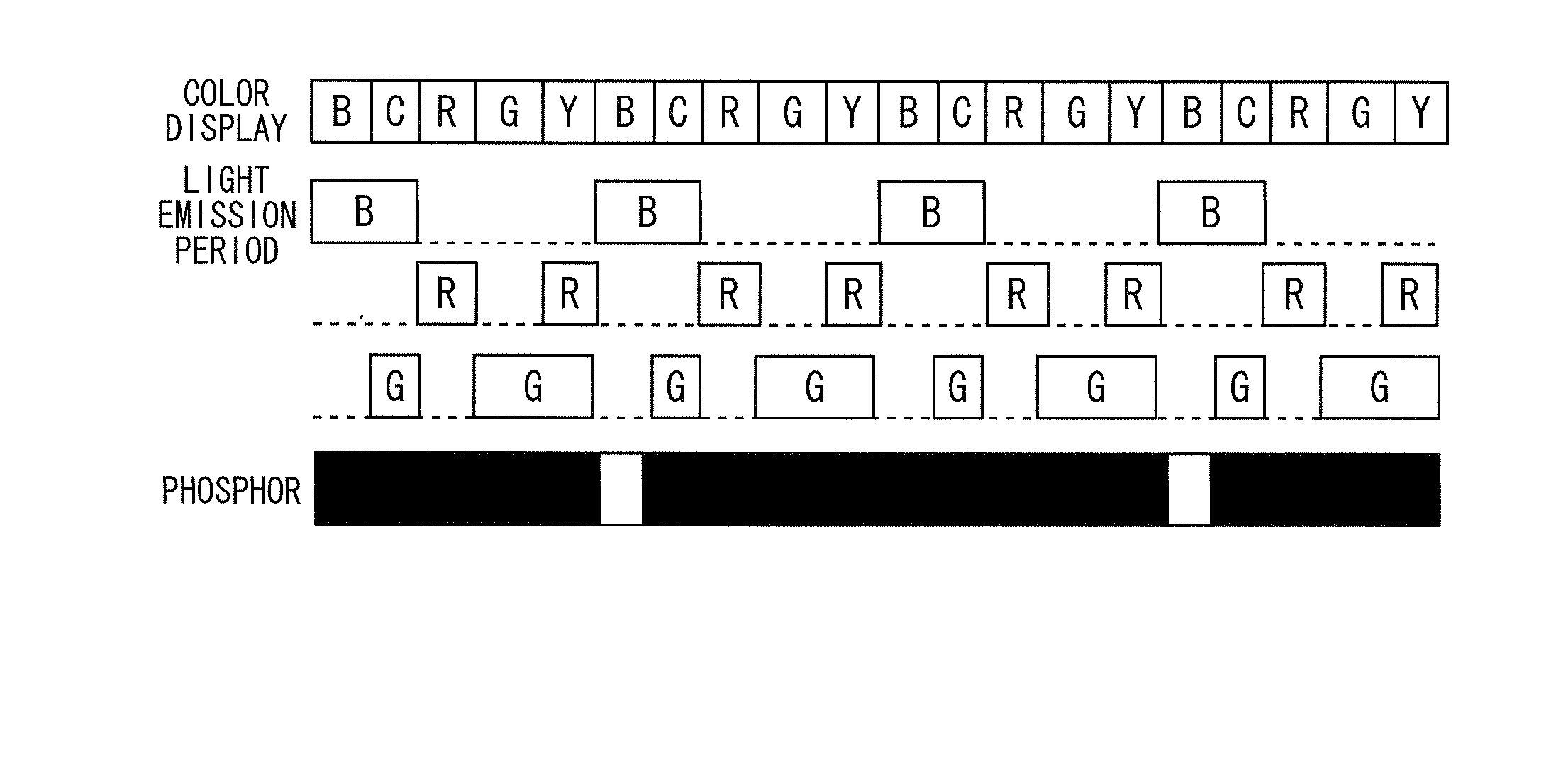
[0043]Since the other structures and operations (a control timing for a light emission period of each light source) is the same as in the first preferred embodiment, description will be omitted.

[0044]As described above, acco...

third preferred embodiment

[0045]FIG. 6 shows front and side views of a phosphor wheel unit provided in a light source apparatus of a projector according to a third preferred embodiment of the present invention.

[0046]As shown in FIG. 6, in a phosphor wheel 44 according to the third preferred embodiment, green phosphors 43a and 43b are disposed in an annular shape on a disk-shaped metallic base material of the phosphor wheel 44. The green phosphors 43a and 43b serve to emit fluorescent light in a green wavelength bandwidth when irradiation with excitation light in a blue wavelength bandwidth is carried out. Moreover, a reflection surface (a mirror surface) for reflecting light is provided on a surface of the metallic base material on which the phosphors 43a and 43b are disposed in the phosphor wheel 44.

[0047]Discontinuous portions 45a and 45b for diffusing and reflecting light are provided between the annular phosphors 43a and 43b.

[0048]The annular phosphors 43a and 43b and the discontinuous portions 45a and ...


PUM


Abstract

A light source apparatus according to the present invention includes a phosphor wheel having a phosphor disposed in an annular shape on a disk-shaped base material, the phosphor serving to emit fluorescent light from excitation light, thereby forming an excitation light source having a predetermined color, and the phosphor having a discontinuous portion in a part of the annular shape, an excitation light source for emitting the excitation light with which a passage position of the circular phosphor is irradiated with respect to the phosphor wheel to be rotatively driven by the wheel motor, and a controller that controls light emission of the light source and the excitation light source synchronously with a position of the discontinuous portion with respect to an irradiation position of the excitation light.

Description

BACKGROUND OF THE INVENTION[0001]1. Field of the Invention[0002]The present invention relates to a light source apparatus and a projector including the light source apparatus.[0003]2. Description of the Background Art[0004]A light source apparatus provided in a projector according to the related art includes a red light source, a blue light source, an excitation light source for emitting excitation light in a blue wavelength bandwidth, a fluorescent light emitting source having a phosphor wheel to be rotatively driven by a motor, and a light source side optical system. An annular fluorescent light emitting region is provided on a disk-shaped metallic base material in the phosphor wheel of the fluorescent light emitting source. A reflection surface for reflecting light is formed in the fluorescent light emitting region, and a layer of a green phosphor for absorbing the excitation light in the blue wavelength bandwidth to emit fluorescent light in a green wavelength bandwidth is provi...

Claims


Application Information

Patent Timeline
IPC IPC(8): F21V9/08G03B21/14
CPCG03B21/142F21V9/08G03B21/204G03B33/08H04N9/3114H04N9/3158H04N9/3164
Inventor YAGYU, SHINJIKOBAYASHI, NOBUTAKAYAMADA, AKIHIROKIDA, HIROSHI
Owner MITSUBISHI ELECTRIC CORP
Features
  • R&D
  • Intellectual Property
  • Life Sciences
  • Materials
  • Tech Scout
  • Unparalleled Data Quality
  • Higher Quality Content
  • 60% Fewer Hallucinations
Learn More