Electrical junction box

a junction box and electric technology, applied in the direction of electrical apparatus casings/cabinets/drawers, transportation and packaging, stacked spaced pcbs, etc., can solve the problems of large space in which the electrical junction box is installed, complicated electric cable routing operation, and insufficient densification of internal circuits, etc., to achieve convenient manufacture of the first printed circuit board, simple shape, and efficient use of printed circuit boards

Inactive Publication Date: 2014-07-17
SUMITOMO WIRING SYST LTD
View PDF10 Cites 13 Cited by
  • Summary
  • Abstract
  • Description
  • Claims
  • Application Information

AI Technical Summary

Benefits of technology

[0007]In the electrical junction box, the internal circuit may be configured by arranging, on the first printed circuit board, an electrical circuit to which the power supply input connector from the battery side is to be connected and arranging, on the second printed circuit board, an electrical circuit to which the output connector to the load side is to be connected, while separating the first printed circuit board and the second printed circuit board from each other, and stacking them. With this, it is possible to downsize the printed circuit boards, as compared with a situation where a connector mounting portion for a power supply input connector and a connector mounting portion for an output connector are arranged in parallel to each other on a single printed circuit board. As a result, it is possible to form the internal circuit while efficiently using the space within the case, and to achieve downsizing / densification of the electrical junction box.
[0017]As an internal circuit, a printed circuit board stack in which a first printed circuit board and a second printed circuit board are disposed so as to face each other and connected to each other is used, and a power supply input connector mounted on the front wall side of a case is configured to be connectable to the first printed circuit board, whereas an output connector mounted on the rear wall side of the case is configured to be connectable to the second printed circuit board. It is thus possible to downsize the internal circuit and improve space efficiency of the case as compared with a situation where the power supply input connector and the output connectors are connected in parallel to one another on one side of the printed circuit board, allowing downsizing and densification of the electrical junction box to be achieved. Further, by mounting the power supply input connector and the output connectors respectively on the facing sides of the case, it is possible to eliminate the need of routing an electric cable of the connector around the electrical junction box while making a U-shaped curve, and to achieve downsizing of a space in which the electrical junction box is installed.

Problems solved by technology

However, densification of the internal circuit is not sufficiently achieved only by such measures for efficiently routing printed wiring patterns, and there are some cases where the printed circuit board has to be made larger in order for a branch circuit and a connector mounting portion to additionally be configured thereon.
Therefore, the routing operation of the electric cable is complicated, and the electric cable, due to its rigidity, inevitably significantly protrudes to the outer peripheral side of the electrical junction box, thus causing a problem that a large space in which the electrical junction box is installed is needed.

Method used


Image

  • Electrical junction box
  • Electrical junction box
  • Electrical junction box

Examples


third embodiment

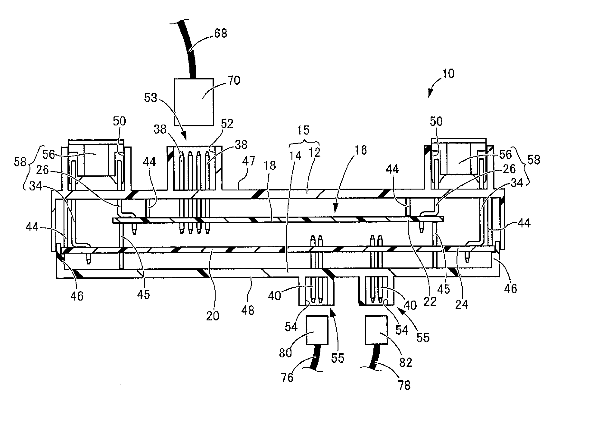
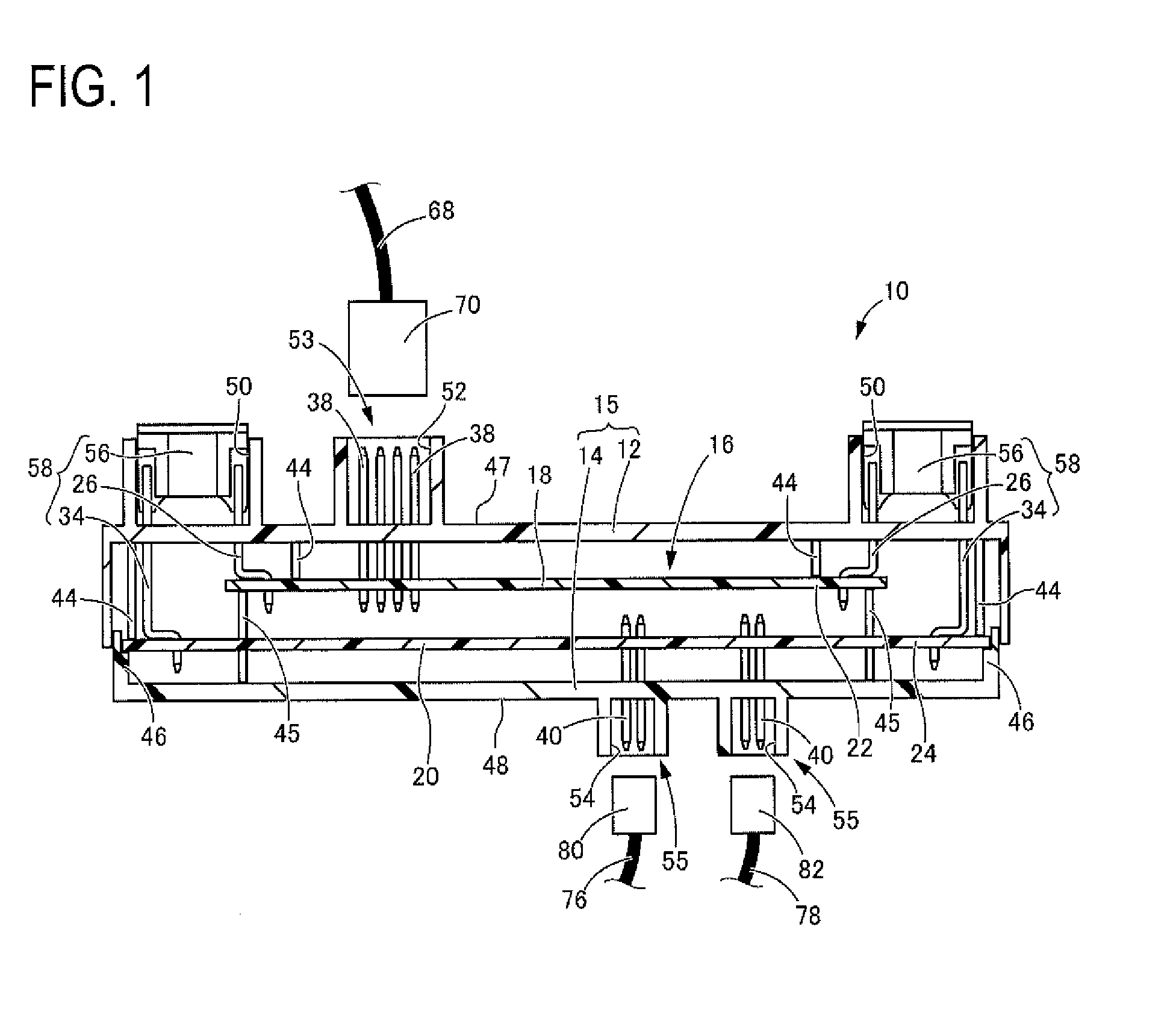
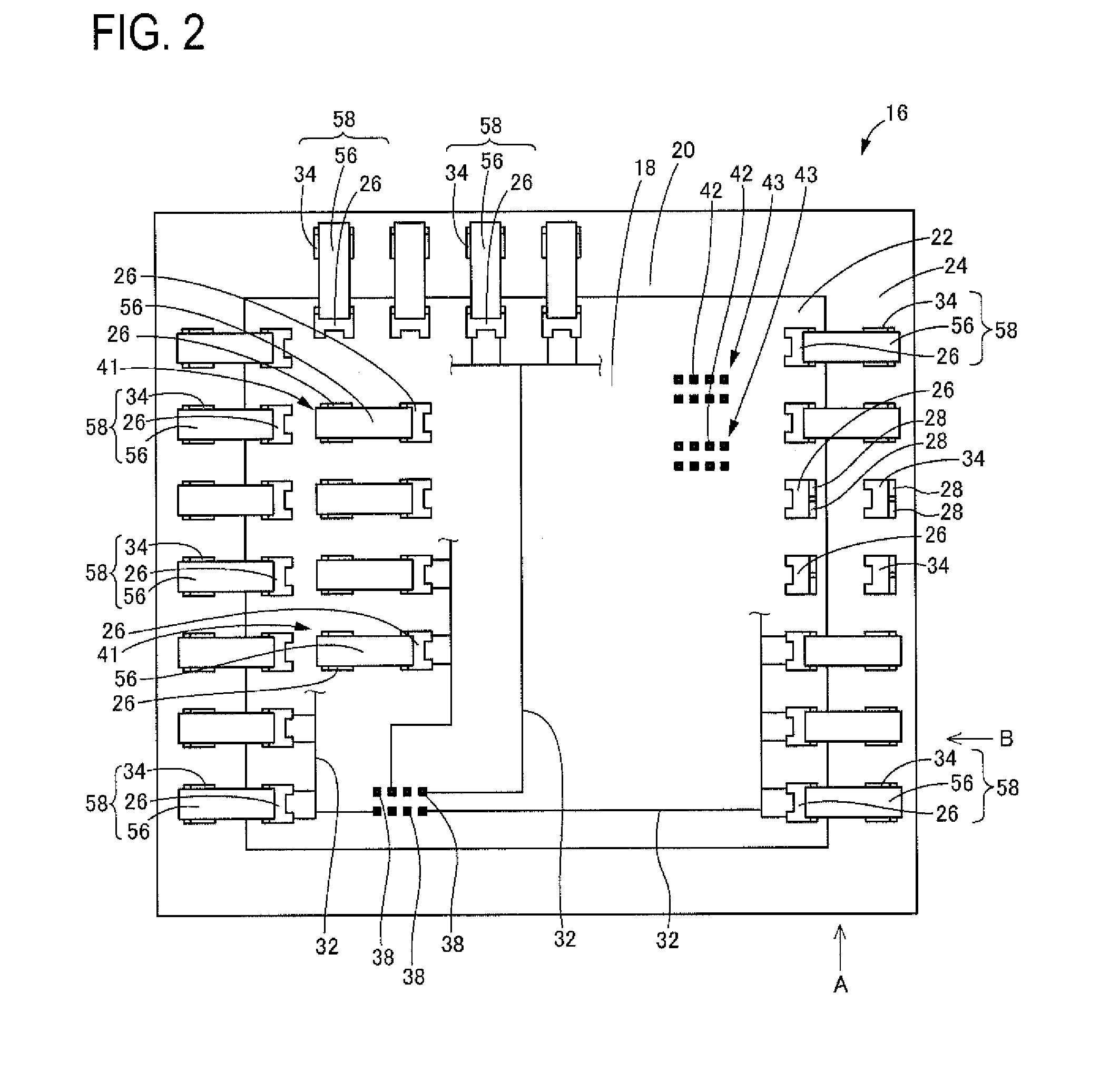
[0048]Next, FIG. 7 shows a top view of a main portion of a printed circuit board. stack 100 that constitutes an internal circuit of an electrical junction box according to a In the present embodiment, a first printed circuit board 18 and a second printed circuit board 20 have substantially the same size, and a peripheral edge portion 22 of the first printed circuit board 18 is arranged above the peripheral edge portion 24 of the second printed circuit board 20 across a gap. A cut-out 102 that is cut inward on the first printed circuit board 18 is formed at the peripheral edge portion 22 of the first printed circuit board 18, and second fork terminals 34 that are vertically provided at the peripheral edge portion 24 of the second printed circuit board 20 project upward of the first printed circuit board 18 while passing through the cut-out 102 and are arranged so as to face the first fork terminals 26 that are vertically provided at the peripheral edge portion 22 of the first printe...

first embodiment

[0051]Further, although the entire peripheral edge portion 22 of the first printed circuit board 18 is located inward of the second printed circuit board 20, a configuration is also possible in which, for example, only one side of the peripheral edge portion 22 is located inward of the second printed circuit board 20, and the first fork terminals 26 and the second fork terminals 34 are arranged only on that side.

[0052]Furthermore, in the above described embodiments, the numbers of the first fork terminals and the second fork terminals, the shape in which the printed wirings are routed, and the like are, of course, merely examples. The numbers of the first fork terminals and the second fork terminals and locations at which they are arranged, the shape in which the printed wirings are routed, and the like are items that can arbitrarily be set.


PUM


Abstract

An electrical junction box is provided in which a printed circuit board is accommodated in a case so as to configure an internal circuit, the electrical junction box achieving downsizing / densification with high space efficiency and simplified routing of electric cables of connectors. As the internal circuit, a printed circuit board stack is used in which a first printed circuit board and a second printed circuit board are arranged so as to face each other. A power supply input connector that is to be mounted to a front wall-side connector mounting portion provided on a front wall of a case is connectable to the first printed circuit board, whereas an output connector that is to be mounted to a rear wall-side connector mounting portion provided on a rear wall of the case is connectable to the second printed circuit board.

Description

[0001]The present application claims priority to Japanese Patent App. No. JP2013-006761, filed on Jan 17, 2013.BACKGROUND ART[0002]As an electrical junction box that is installed in an automobile, an electrical junction box is known in which a printed circuit board is accommodated inside the electrical junction box so as to constitute an internal circuit. In such an electrical junction box, as disclosed in, for example, JP 2008-295221 A, a power supply input connector that is arranged upstream and configured to supply power and signals, and output connectors configured to output—to various types of loads—power supply and signals branched via printed wirings are connected to the printed circuit board, thereby achieving efficient branching / distribution of power supply and the like.[0003]Due to an increase in the number of in-vehicle electrical components, the number of branch circuits on the printed circuit board and the number of connectors connected to the printed circuit board are ...

Claims


Application Information

Patent Timeline
Patent Type & Authority Applications(United States)
IPC IPC(8): H05K1/11
CPCH05K1/11B60R16/0238H05K1/144H05K2201/042H05K2201/10303H05K2201/10181H02G3/08
Inventor SHI, WENJIE
Owner SUMITOMO WIRING SYST LTD
Why Eureka
Try Eureka