Optical polarization demultiplexing for a coherent-detection scheme

Active Publication Date: 2014-07-17
ALCATEL LUCENT SAS
View PDF4 Cites 20 Cited by
  • Summary
  • Abstract
  • Description
  • Claims
  • Application Information

AI Technical Summary

Problems solved by technology

However, a major challenge of this particular transmission format is the need for fast and precise polarization tracking and, in the case of homodyne detection, for phase and carrier-frequency locking of the optical local-oscillator signal.

Method used


Image

  • Optical polarization demultiplexing for a coherent-detection scheme
  • Optical polarization demultiplexing for a coherent-detection scheme
  • Optical polarization demultiplexing for a coherent-detection scheme

Examples


Embodiment Construction

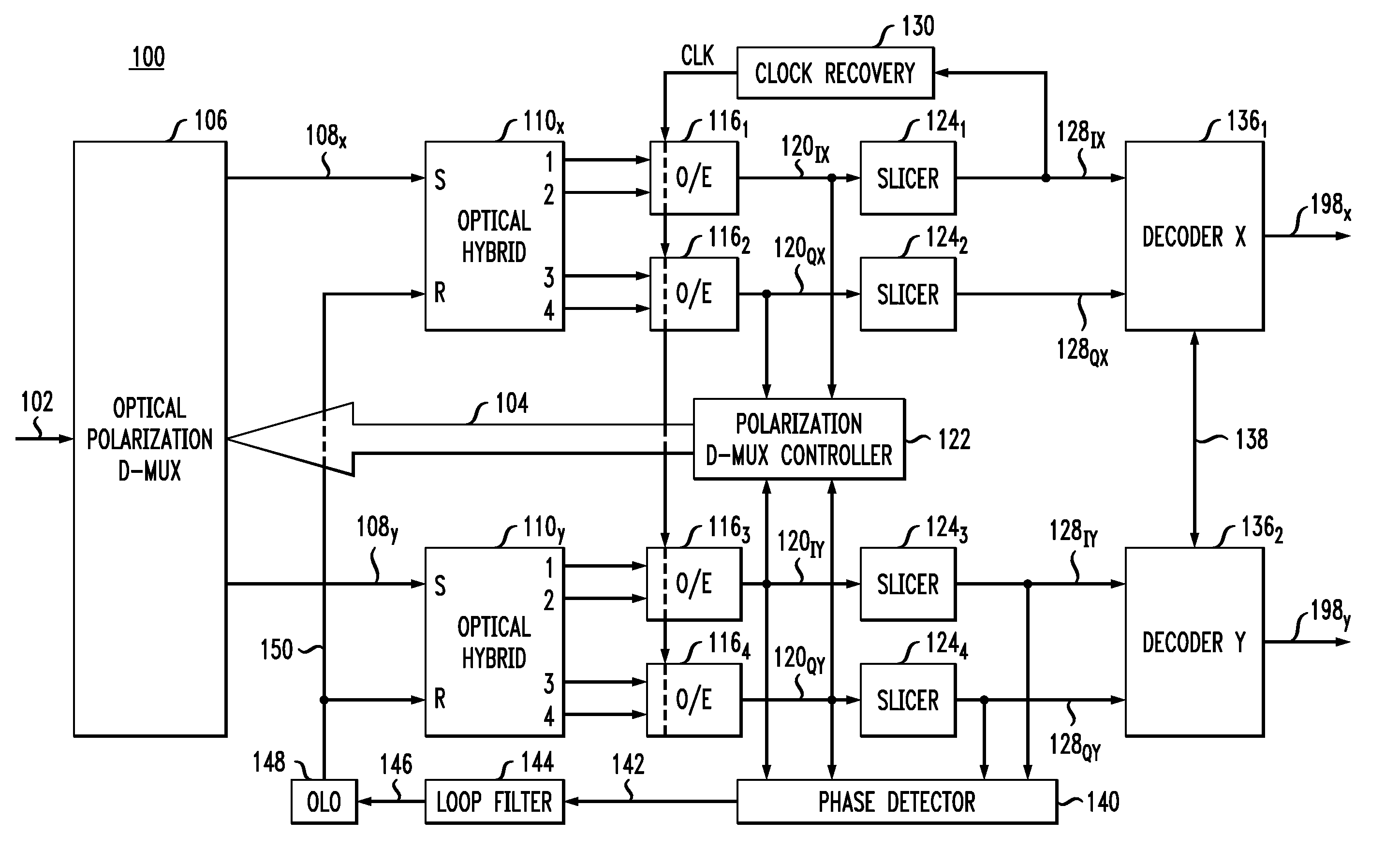
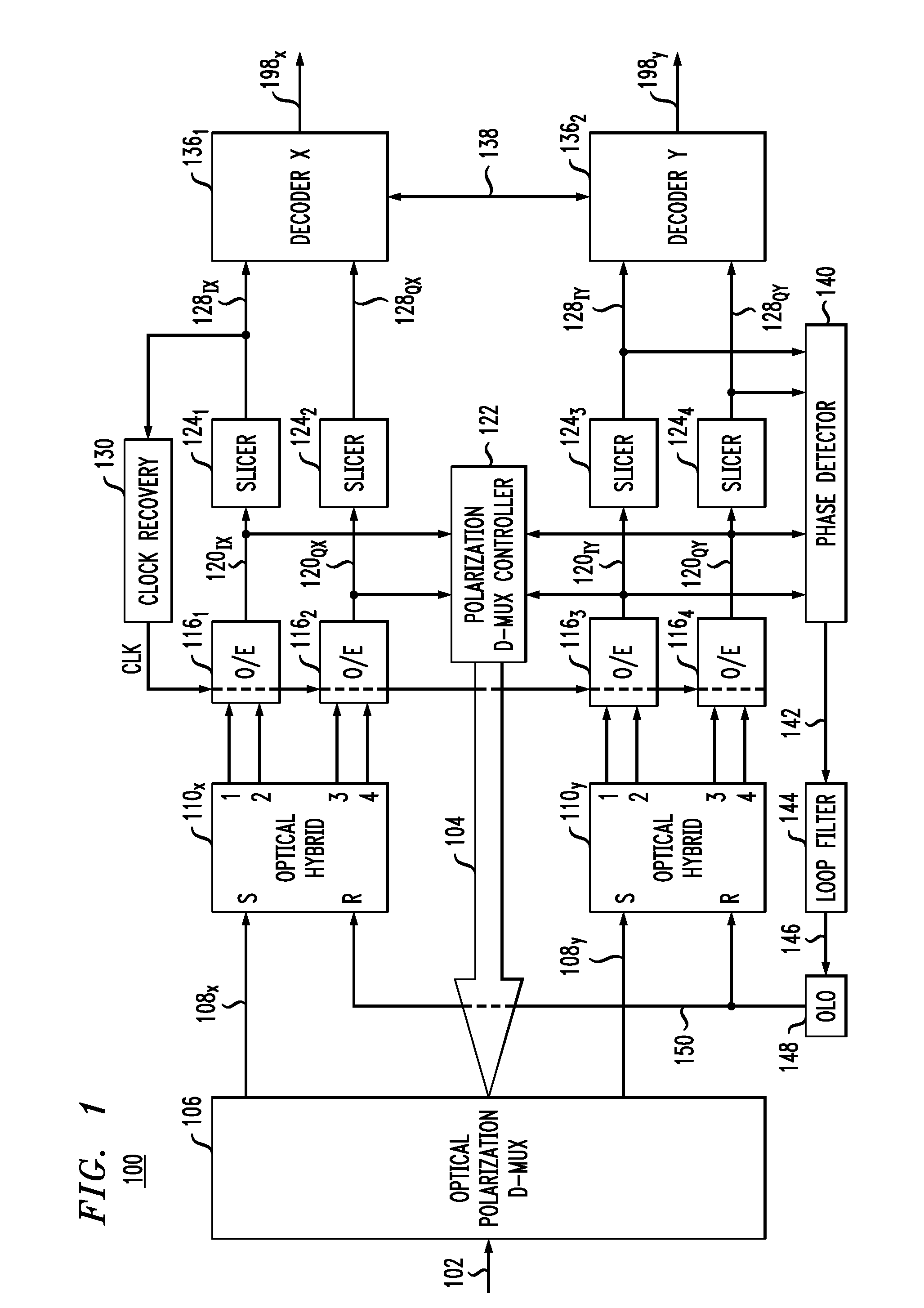
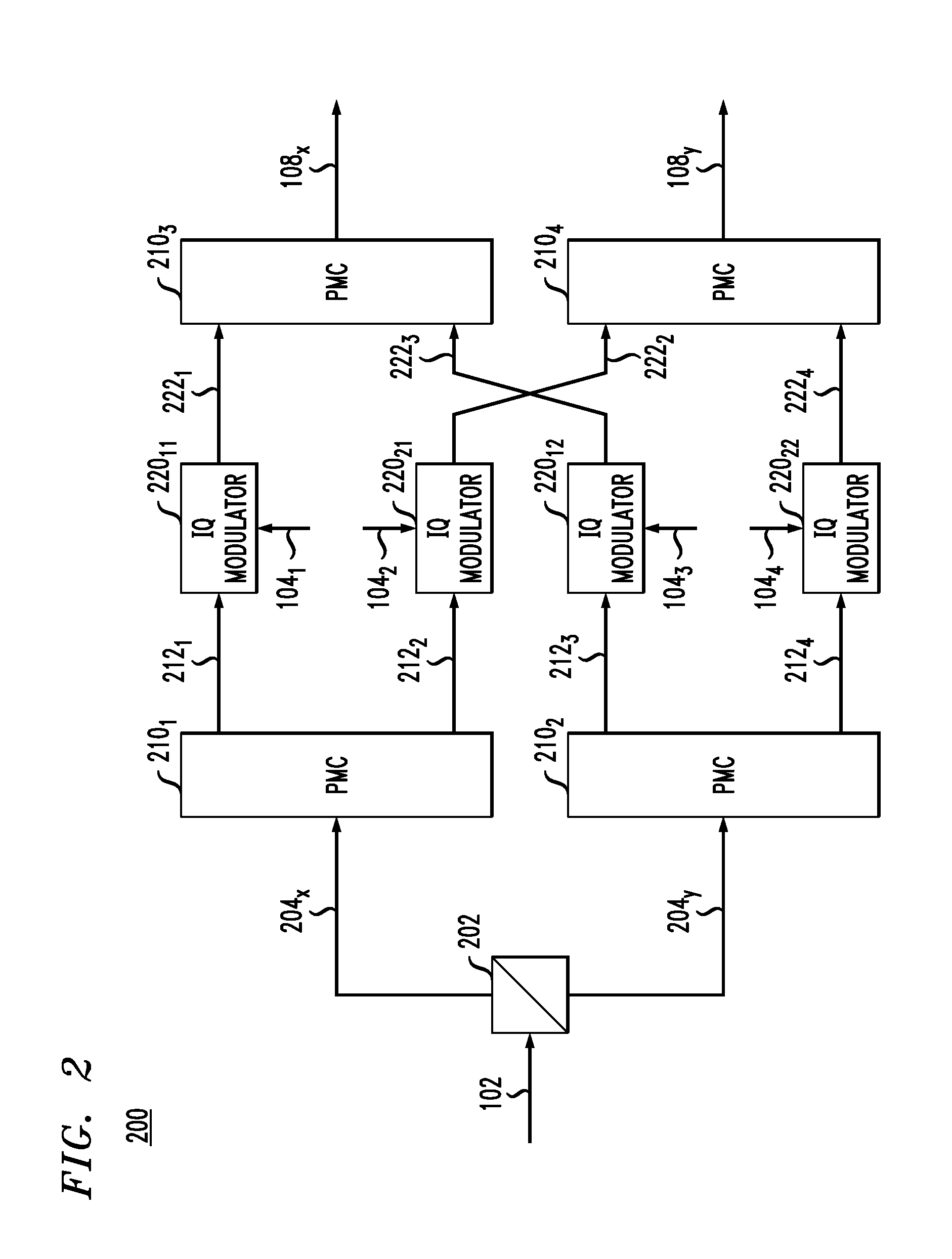
[0007]Disclosed herein are various embodiments of an optical receiver having a plurality of optical IQ modulators arranged in a butterfly configuration and configured to operate as an optical polarization de-multiplexer. The optical receiver further has (i) an opto-electric circuit configured to apply optical homodyne detection to an optical input signal received by the optical receiver and (ii) a controller configured to generate one or more control signals for driving the IQ modulators based on one or more electrical feedback signals received from the opto-electric circuit.

[0008]According to one embodiment, provided is an apparatus comprising: a first optical IQ modulator configured to modulate a first portion of a first polarization of an optical polarization-division-multiplexed (PDM) signal to generate a first modulated optical signal; a second optical IQ modulator configured to modulate a second portion of the first polarization of the optical PDM signal to generate a second m...


PUM


Abstract

An optical receiver having a plurality of optical IQ modulators arranged in a butterfly configuration and configured to operate as an optical polarization de-multiplexer. The optical receiver further has (i) an opto-electric circuit configured to apply optical homodyne detection to an optical input signal received by the optical receiver and (ii) a controller configured to generate one or more control signals for driving the IQ modulators of the plurality based on one or more electrical feedback signals received from the opto-electric circuit.

Description

CROSS-REFERENCE TO RELATED APPLICATIONS[0001]The subject matter of this application is related to that of U.S. patent application Ser. No. 1______, by Noriaki Kaneda, attorney docket reference 813146-US-NP, filed on the same date as the present application, and entitled “GENERATION OF AN OPTICAL LOCAL-OSCILLATOR SIGNAL FOR A COHERENT-DETECTION SCHEME,” which is incorporated herein by reference in its entirety.BACKGROUND[0002]1. Field[0003]The present disclosure relates to optical communication equipment and, more specifically but not exclusively, to coherent detection of modulated optical signals.[0004]2. Description of the Related Art[0005]This section introduces aspects that may help facilitate a better understanding of the invention(s). Accordingly, the statements of this section are to be read in this light and are not to be understood as admissions about what is in the prior art or what is not in the prior art.[0006]Coherent detection is used in optical transport systems, for e...

Claims


Application Information

Patent Timeline
Patent Type & Authority Applications(United States)
IPC IPC(8): H04J14/06
CPCH04J14/06H04B10/6166H04B10/614
Inventor KANEDA, NORIAKI
Owner ALCATEL LUCENT SAS
Why Eureka
Try Eureka