Ball seat apparatus and method

a technology of casing and apparatus, which is applied in the direction of sealing/packing, liquid fuel engines, borehole/well accessories, etc., can solve the problems of limiting the chances of inadvertent cementing of the motor in place, and achieve the effect of limiting the chances of inadvertent cementing of the motor and preventing damage to the power section

Active Publication Date: 2014-07-17
WEATHERFORD TECH HLDG LLC
View PDF16 Cites 10 Cited by
  • Summary
  • Abstract
  • Description
  • Claims
  • Application Information

AI Technical Summary

Benefits of technology

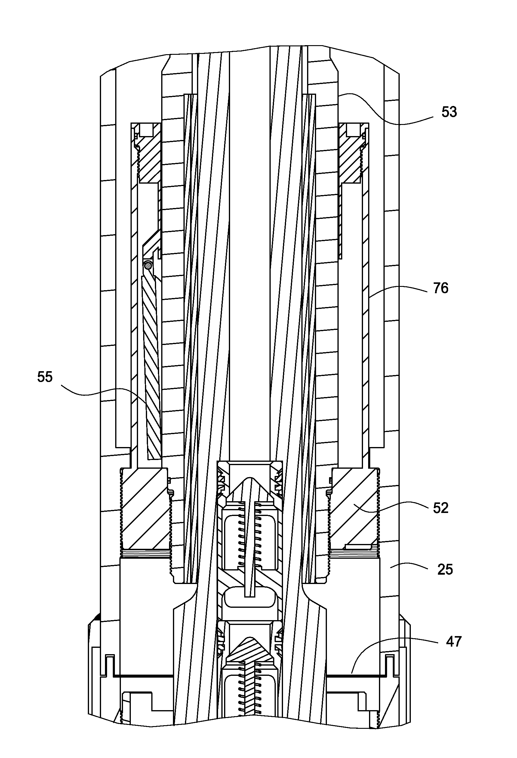
[0008]The motor may also include features for cementing either around or through the drilling motor. In one embodiment, a cement diverter mechanism is used to alter the flow path for cementing purposes. Separate flow paths are available for drilling fluid flow during drilling mode and cement flow during cementing mode. These features limit the chances of inadvertently cementing the motor in place. In another embodiment, the power section of the drilling motor is sealed off prior to pumping cement, in order to prevent damage to the power section from hardened cement.

Problems solved by technology

These features limit the chances of inadvertently cementing the motor in place.

Method used


Image

  • Ball seat apparatus and method
  • Ball seat apparatus and method
  • Ball seat apparatus and method

Examples


Embodiment Construction

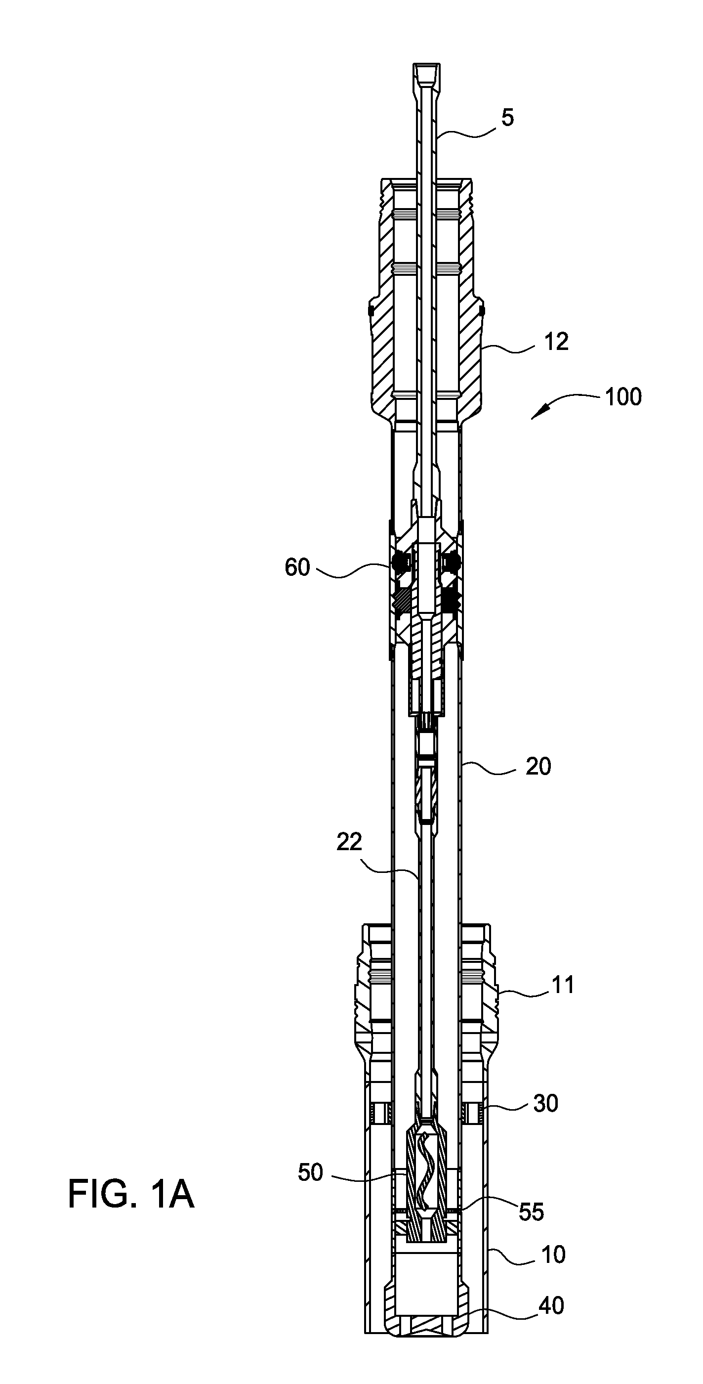
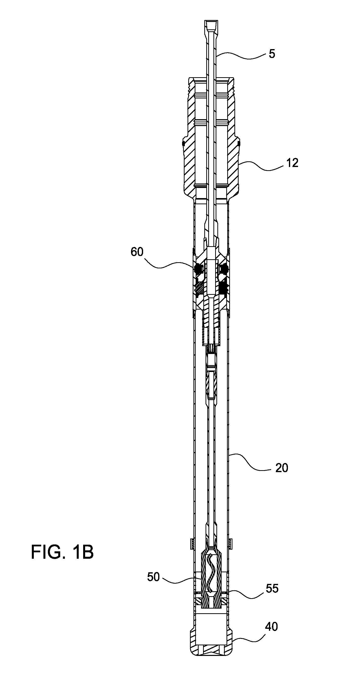
[0034]Embodiments of the present invention generally relates to a casing drilling system. In one embodiment, the system includes a conductor casing coupled to a surface casing and the coupled casings can be run concurrently. In one trip, the system will jet-in the conductor casing and a low pressure wellhead housing, unlatch the surface casing from the conductor casing, drill the surface casing to target depth, land a high pressure wellhead housing, cement, and release. The system includes a drill bit that may be powered by a retrievable downhole motor which rotates the drill bit independently of the surface casing string. In another embodiment, the system may also include the option of rotating the drilling bit from surface.

[0035]An exemplary casing drilling method is disclosed in U.S. patent application Ser. No. 12 / 620,581, which application is incorporated herein in its entirety.

[0036]An exemplary subsea casing drilling system is disclosed in U.S. provisional patent application S...


PUM


Abstract

A ball seat assembly includes a tubular having a bore therethrough; an entry port in fluid communication with the bore; a plurality of exit ports in fluid communication with the entry port; a ball seat disposed in the each of the plurality of exit ports, wherein the ball seat is configured to receive a ball to block fluid flow through the respective exit port; and a diverter configured to block fluid flow through the bore and direct fluid flow from the bore to the entry port.

Description

BACKGROUND OF THE INVENTION[0001]1. Field of the Invention[0002]The present invention generally relates to an apparatus and method for casing drilling. More particularly, the invention relates to a ball seat apparatus and method for casing drilling.[0003]2. Description of the Related Art[0004]In the oil and gas producing industry, the process of cementing casing into the wellbore of an oil or gas well generally comprises several steps. For example, a conductor pipe is positioned in the hole or wellbore and may be supported by the formation and / or cemented. Next, a section of a hole or wellbore is drilled with a drill bit which is slightly larger than the outside diameter of the casing which will be run into the well.[0005]Thereafter, a string of casing is run into the wellbore to the required depth where the casing lands in and is supported by a well head in the conductor. Next, cement slurry is pumped into the casing to fill the annulus between the casing and the wellbore. The ceme...

Claims


Application Information

Patent Timeline
Patent Type & Authority Applications(United States)
IPC IPC(8): E21B34/06
CPCE21B34/06E21B4/02E21B7/20E21B21/10E21B33/14E21B34/14E21B23/0413
Inventor TWARDOWSKI, ERIC M.
Owner WEATHERFORD TECH HLDG LLC
Why Eureka
Try Eureka