Controlled-Impedence Cable Termination Using Compliant Interconnect Elements

Active Publication Date: 2014-07-17
ARDENT CONCEPTS INC
View PDF5 Cites 12 Cited by
  • Summary
  • Abstract
  • Description
  • Claims
  • Application Information

AI Technical Summary

Benefits of technology

[0006]The present invention is an apparatus and method for terminating a controlled-impedance cable that uses a c

Problems solved by technology

The SMA connectors, while being generally the same impedance environment as the cable, have impedance mismatches which cause high-frequency attenuation at the point of interface between the cable and the connector and the connector and its working environment, such as like a PCB.
Additionally, these cable terminations often require through holes in PCB's for mounting and, consequently

Method used


Image

  • Controlled-Impedence Cable Termination Using Compliant Interconnect Elements
  • Controlled-Impedence Cable Termination Using Compliant Interconnect Elements
  • Controlled-Impedence Cable Termination Using Compliant Interconnect Elements

Examples


Embodiment Construction

[0086]The present application hereby incorporates by reference U.S. Provisional Patent Application No. 61 / 550,543 in its entirety, on which portions of this application are based.

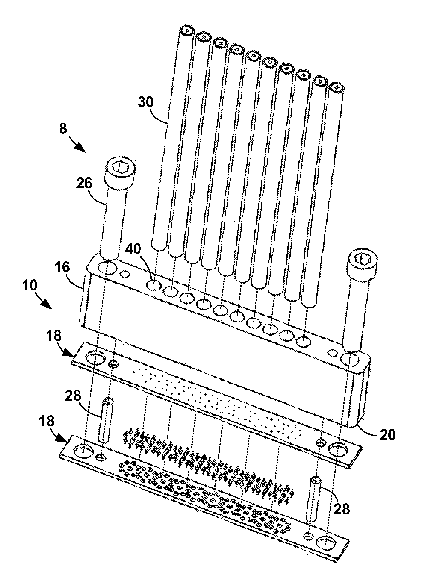
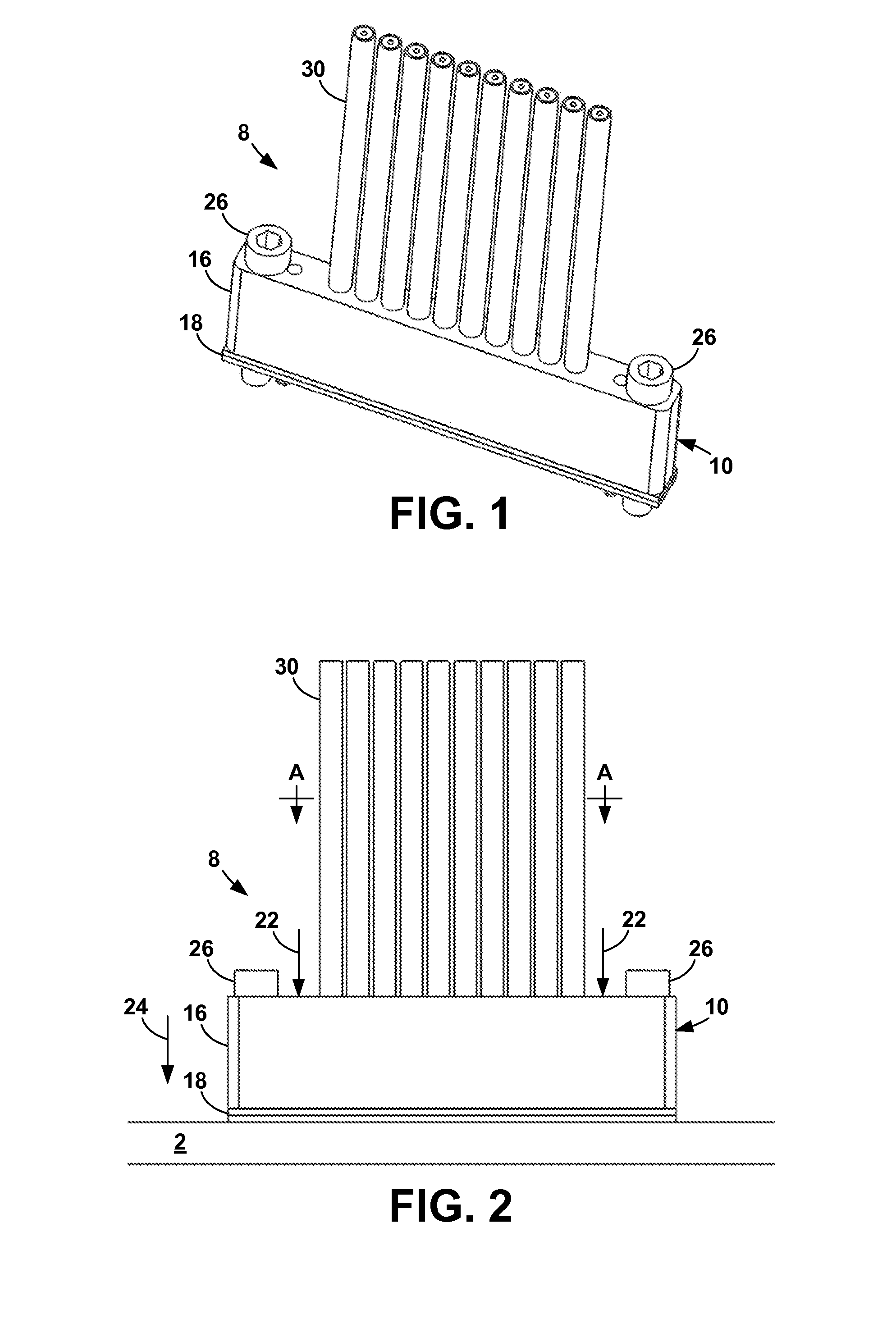
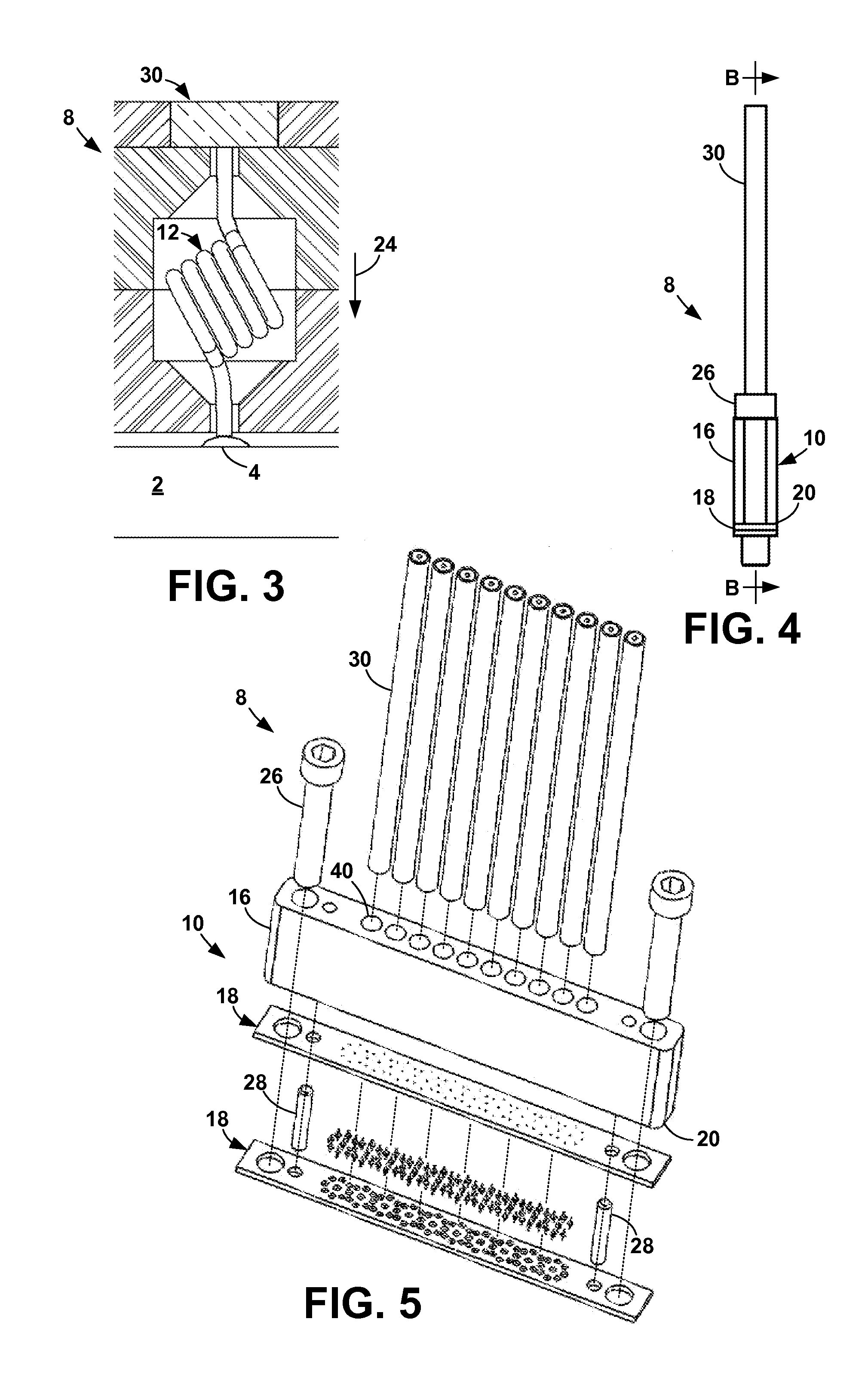
[0087]The present invention is an apparatus and method for terminating a controlled-impedance cable that minimizes detrimental electrical effects of the termination by using a compliant or compressible contact element at the point of termination. With the present invention, impedance mismatches are minimized, allowing the cable to be more useful in high-frequency signal ranges. The present invention can be used with any cable structure where the impedance between the inner conductor(s) and the ground shield is controlled.

[0088]In addition, the present invention increases the density at which the controlled-impedance cables can be used. That is, with the present invention, more cables can be terminated in a given amount of space than with terminations of the prior art. Further, the interface between the comp...


PUM

PropertyMeasurementUnit
Angleaaaaaaaaaa
Lengthaaaaaaaaaa
Electrical conductivityaaaaaaaaaa

Abstract

An apparatus for terminating a controlled-impedance cable using compliant electrical contacts to provide an interface to another device. The terminator includes a conductive ground block for securing the cable by its ground shield and providing a common ground. Once the cable is anchored in the ground block, the block face and cable ends are dressed to make a reliable electrical contact with the compliant signal contact that electrically connects the cable center conductor to the device. An insulating or conductive plate mounted to the ground block holds the signal contact and optional ground contacts that electrically connect the ground block to the ground plane of the device. The ground contacts surround the signal contact in a pattern that closely mimics the impedance environment of the cable. When using a conductive plate, the signal contact is insulated from the plate by an insulating centering plug or a non-conductive coating.

Description

TECHNICAL FIELD[0001]The present invention relates to electrical cable terminations, more particularly, to controlled impedance cable terminations which are generally used to transmit high-frequency signals in electronic equipment.BACKGROUND ART[0002]The purpose of a cable termination is to provide an interconnect from the cable to the electrical device and to provide a separable electrical interconnection between the cable and its operating environment. The characteristic of separability means that the cables are not interconnected by permanent mechanical means, such as soldering or bonding, but by temporary mechanical means.[0003]Currently cables are terminated using a conventional type connector which is also controlled-impedance, such as an SMA (SubMiniature Version A) connector, or the cables are soldered to a printed circuit board (PCB) which is then separably connected to the working environment. The SMA connectors, while being generally the same impedance environment as the ...

Claims


Application Information

Patent Timeline
IPC IPC(8): H01R24/38H01R43/00
CPCH01R43/00H01R24/38H01R12/75H01R13/2421H01R12/714H01R13/65912H01R12/79H01R13/6473H01R13/6633Y10T29/53243H01R13/648H01R13/6581H02G1/14
Inventor VINTHER, GORDON ADIAZ, SERGIOHEBERT, JEFFREY G.
Owner ARDENT CONCEPTS INC
Why Eureka
Try Eureka