Chain tensioner

a chain tensioner and chain technology, applied in the direction of belts/chains/gearrings, mechanical instruments, belts/chains/gears, etc., can solve the problems of difficult universal use of the tensioner, difficulty in adjusting the tensioner, so as to achieve a wider range of flow resistance, simplify the structure, and reduce the effect of friction

Active Publication Date: 2014-07-17
TSUBAKIMOTO CHAIN CO
View PDF5 Cites 22 Cited by
  • Summary
  • Abstract
  • Description
  • Claims
  • Application Information

AI Technical Summary

Benefits of technology

[0035]Therefore, the amount of oil leaking to the outside from the distal end of the plunger through the gap between the plunger and the plunger bore is further reduced irrespective of the position of the oil supply hole or the mounting orientation of the chain tensioner itself, or of the rotational position of the plunger, so that much more oil can be recovered into the oil reservoir chamber.
[0036]The distance of the contact surface leak groove can be made longer as appropriate, so that the flow resistance can be set in a wider range as required.
[0037]With the structure as set forth in claim 7, the other end of the coil spring is seated in the plunger body, so that there is no need to provide a long space for the oil pressure chamber in the plunger bore to accommodate the coil spring, and the entire tensioner can be made shorter and smaller.
[0038]With the structure as set forth in claim 8, the other end of the coil spring is seated on the outer flange of the retainer in the plunger body, so that the check valve can be disposed inside the coil spring. As there is no need to provide a long space for the oil pressure chamber in the plunger bore, the entire tensioner can be made shorter and smaller.
[0039]With the structure as set forth in claim 9, one surface on the check valve side of the reserve tube functions also as the ball seat of the check valve. As the structure is further simplified, production is easier and the production cost can be reduced.
[0040]With the structure as set forth in claim 10, one end of the coil spring seated on the bottom of the plunger bore is restricted from moving sideways by the tapered surface, so that looseness or displacement of the coil spring in the lateral direction inside the oil pressure chamber or the cylindrical recess can be prevented to allow smooth reciprocation of the plunger. Also, as the tensioner requires less space for allowing lateral displacement, it can be made shorter and smaller.

Problems solved by technology

However, this configuration cannot be applied to a design in which oil is supplied laterally.
Universal use of the tensioner was difficult because of the restrictions on the position of the oil supply hole (oil supply hole 122) or mounting orientation of the chain tensioner.
Another problem was that the plunger structure was made complex because of the anti-rotation mechanism that was essential to stop rotation of the plunger.
The production process was therefore complex because the plunger needed machining in many parts, and also the cost was increased because of material limitations.

Method used


Image

  • Chain tensioner
  • Chain tensioner
  • Chain tensioner

Examples


embodiment 1

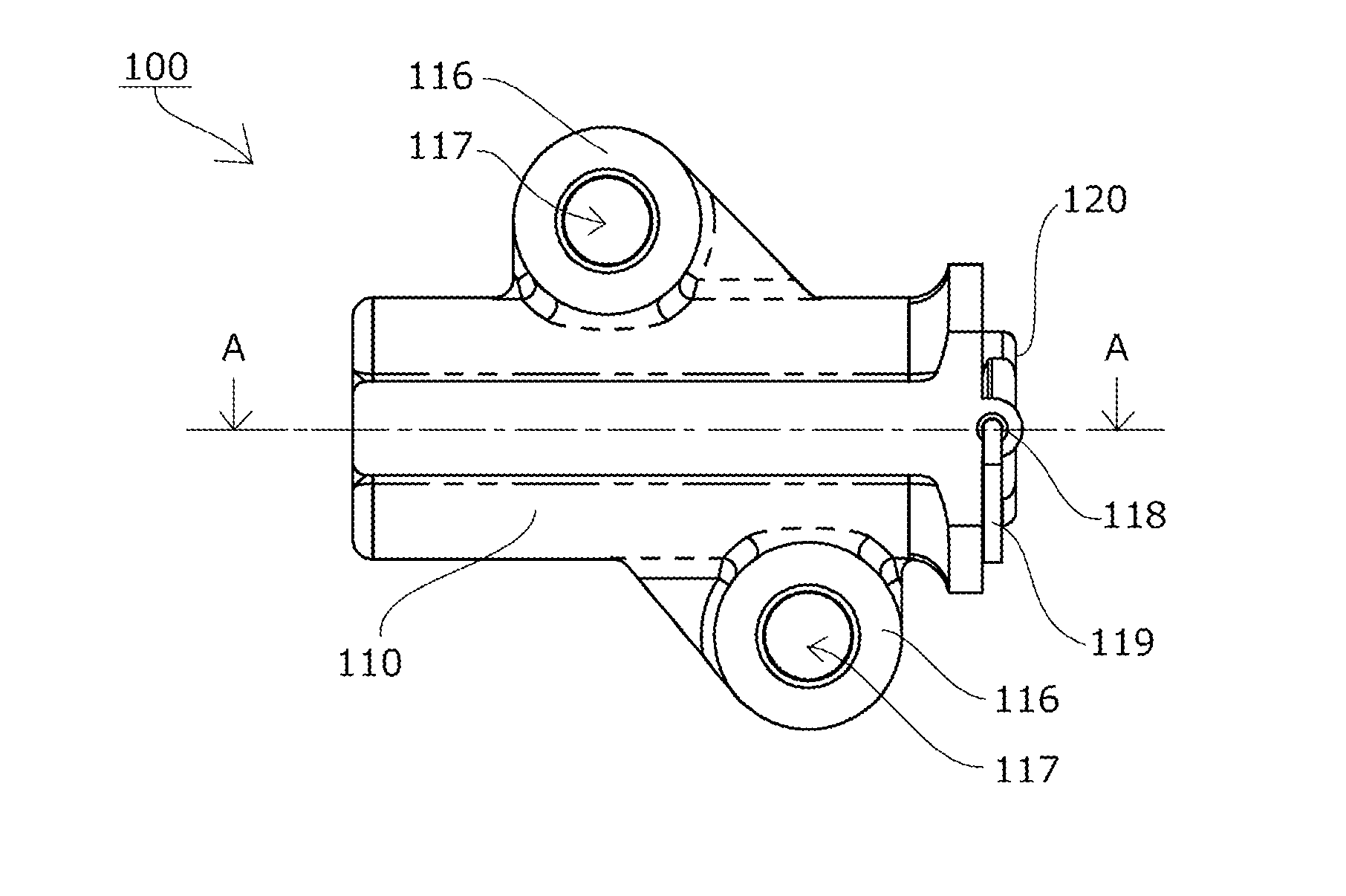
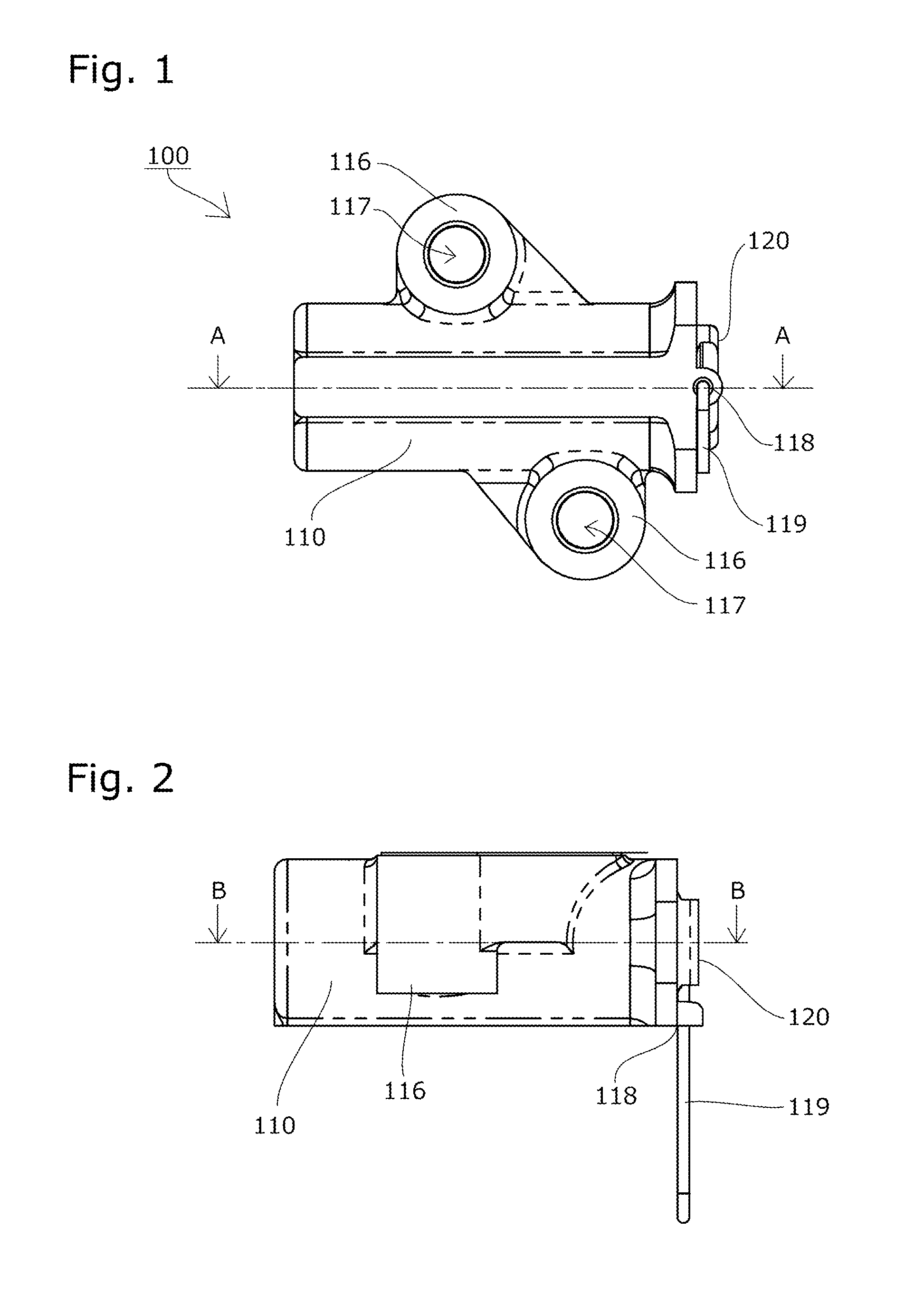
[0062]A chain tensioner 100 according to a first embodiment of the present invention will be described with reference to the drawings.

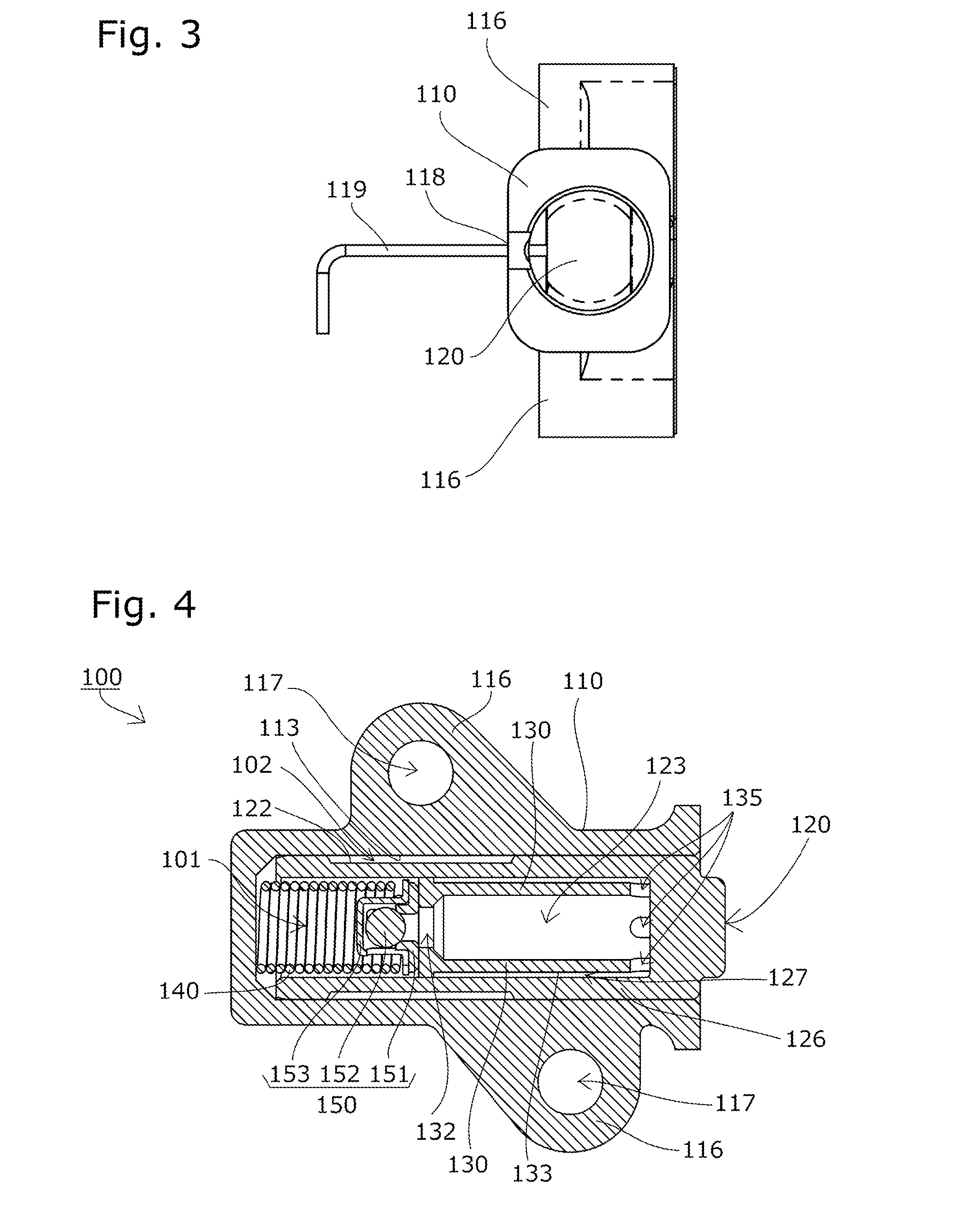
[0063]The chain tensioner 100 according to a first embodiment of the present invention includes, as shown in FIG. 1 to FIG. 8, a tensioner body 110 having a cylindrical plunger bore 111 with an open end, a cylindrical plunger 120 slidable within the plunger bore 111, and a coil spring 140 that is an urging unit accommodated inside an oil pressure chamber 101 formed between the plunger bore 111 and the rear end of the plunger 120 such as to be able to expand and contract and to urge the plunger 120 outward.

[0064]The chain tensioner 100 according to this embodiment is securely mounted inside an engine having a chain guide mechanism. For this purpose, the tensioner body 110 has mounting parts 116 with mounting holes 117 for bolts or the like to pass through as shown in FIG. 1 to FIG. 6.

[0065]An oil supply hole 114 is formed in the cylindrical surface 113...

embodiment 2

[0097]The chain tensioner 200 according to a second embodiment of the present invention does not include an outer leak groove in the outer circumference of the plunger body 126 on the oil pressure chamber 101 side, but instead includes inner leak grooves 136 in the large-diameter part 134 of the reserve tube 130 as shown in FIG. 10 and FIG. 11, as compared to the chain tensioner 100 according to the previously described first embodiment (reference numerals in the drawings are the same as those of the first embodiment).

[0098]In this embodiment, the reserve tube 130 is formed with inner leak grooves 136 at four positions of the large-diameter part 134 as shown in FIG. 11, so that oil can flow from the oil pressure chamber 101 through the inner leak grooves 136 into the internal supply cavity 127.

[0099]No leak grooves are formed in the outer circumference on the oil pressure chamber 101 side of the plunger body 126.

[0100]The chain tensioner is configured the same in other respects as t...

embodiment 3

[0106]The chain tensioner 300 according to a third embodiment of the present invention does not include an outer leak groove in the outer circumference of the plunger body 126 on the oil pressure chamber 101 side, but instead includes end face leak grooves 137 and seat leak grooves 154 in the end face 131 of the reserve tube 130 and in the surface on the reserve tube 130 side of the ball seat 151, respectively, as shown in FIG. 12, FIG. 13A, and FIG. 13B, as compared to the chain tensioner 200 according to the previously described second embodiment (reference numerals in the drawings are the same as those of the first embodiment).

[0107]In this embodiment, the reserve tube 130 is formed with end face leak grooves 137 at three radial positions in the end face 131, which extend from the outer circumference to the oil hole 132, as shown in FIG. 13A, and with seat leak grooves 154 at three radial positions similarly in the surface on the reserve tube 130 side of the ball seat 151, as sho...


PUM


Abstract

To provide a chain tensioner that has a simple structure, is universally usable, is capable of supplying sufficient and necessary oil when restarted after a long time after the stop of oil supply, enables reduction in entire length and size, and enables easy production and reduction in production cost. An urging unit 140 provided in an oil pressure chamber 101 to be expandable and contractible urges a plunger 120 outward from a plunger bore 111 in a tensioner body 110 of the chain tensioner 100. The plunger 120 includes a plunger body 126, a check valve 150 provided inside the body, and a reserve tube 130 that has an oil reservoir chamber 123 communicating with the oil pressure chamber 101 through an oil hole 132.

Description

BACKGROUND OF THE INVENTION[0001]1. Field of the Invention[0002]The present invention relates to a chain tensioner that includes a tensioner body having a cylindrical plunger bore with an open end, a cylindrical plunger slidable within the plunger bore, and an urging unit accommodated inside an oil pressure chamber formed between the plunger bore and the rear end of the plunger such as to be able to expand and contract and to urge the plunger outward, the chain tensioner being capable of maintaining suitable tension of a chain.[0003]2. Description of the Related Art[0004]Chain tensioners are commonly used for maintaining suitable tension of chains. In a chain guide mechanism that slidably guides a transmission chain such as an endless roller chain passing over respective sprockets of a crankshaft and a cam shaft inside an engine room with a guide shoe, for example, it is known to urge a pivoting chain guide having the guide shoe with a chain tensioner to maintain suitable tension.[0...

Claims


Application Information

Patent Timeline
Patent Type & Authority Applications(United States)
IPC IPC(8): F16H7/08
CPCF16H7/08F16H2007/0859F16H2007/0806F16H2007/0812F16H2007/0891F16H7/0848F16H2007/0878
Inventor KUREMATSU, YUJI
Owner TSUBAKIMOTO CHAIN CO
Why Eureka
Try Eureka