Ceramic element and method of manufacturing the same

Inactive Publication Date: 2014-07-24
NGK INSULATORS LTD
View PDF5 Cites 4 Cited by
  • Summary
  • Abstract
  • Description
  • Claims
  • Application Information

AI Technical Summary

Benefits of technology

The patent text describes a technique for coating ceramic surfaces with various layers to improve performance. The technique involves forming a first coating layer on the front surface of the ceramic body and a second coating layer on the back surface. This results in a continuous coating layer that covers the ceramic body from its front surface to its side surface and from its side surface to its back surface, without any break or discontinuity. This prevents detachment of the coating layer and eliminates ceramic particles that can be shed during use. The technique effectively prevents damage to the ceramic body during machining and provides better protection against detachment of the coating layer.

Problems solved by technology

With prior art techniques for coating the machined surface of a ceramic body with a coating layer, there has been the problem that the coating layer that has been applied can easily become detached from the machined surface of the ceramic body.
If the coating layer on a ceramic element becomes detached therefrom, then it becomes impossible to prevent subsequent shedding of ceramic particles from the ceramic element.

Method used


Image

  • Ceramic element and method of manufacturing the same
  • Ceramic element and method of manufacturing the same
  • Ceramic element and method of manufacturing the same

Examples


first embodiment

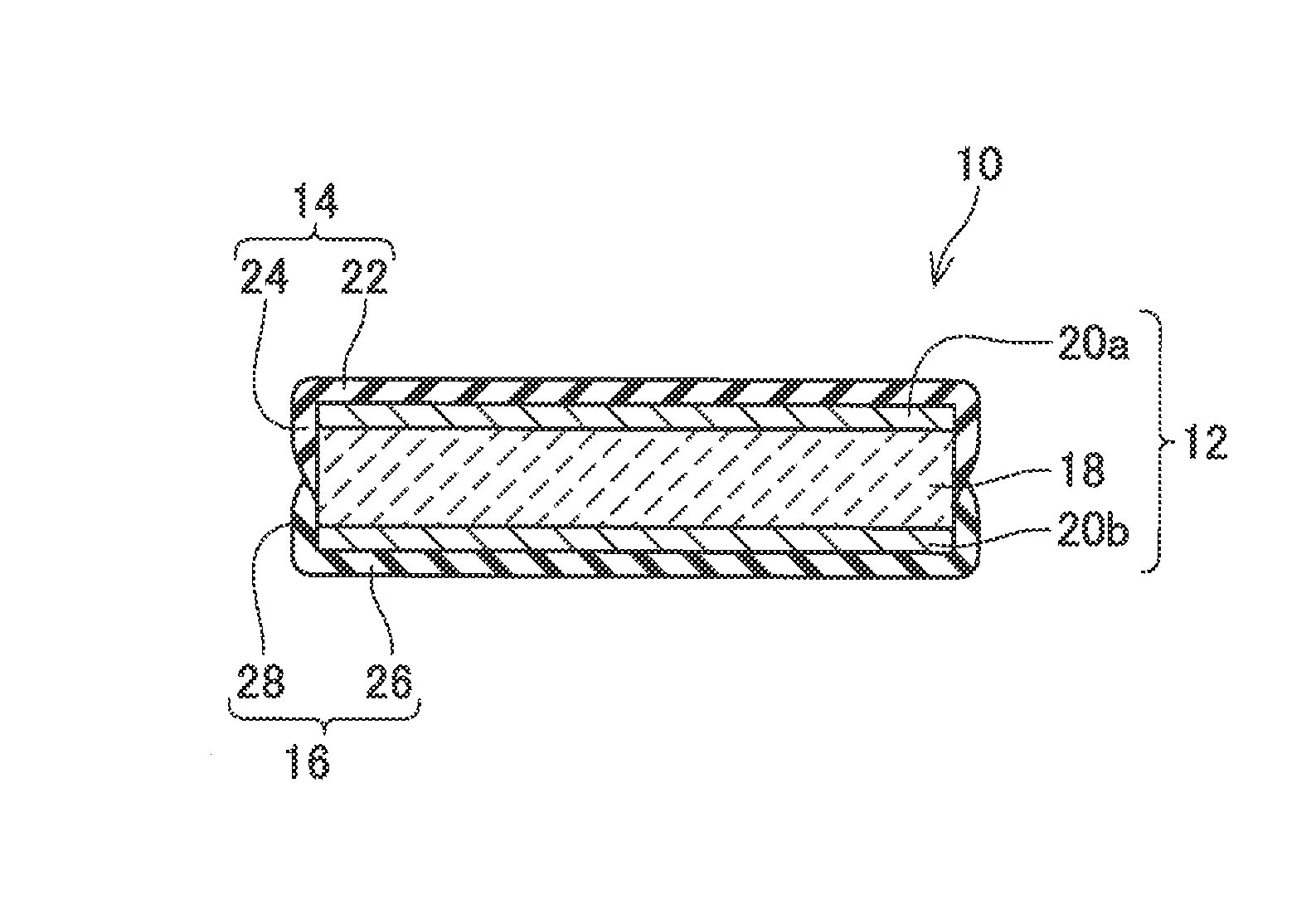
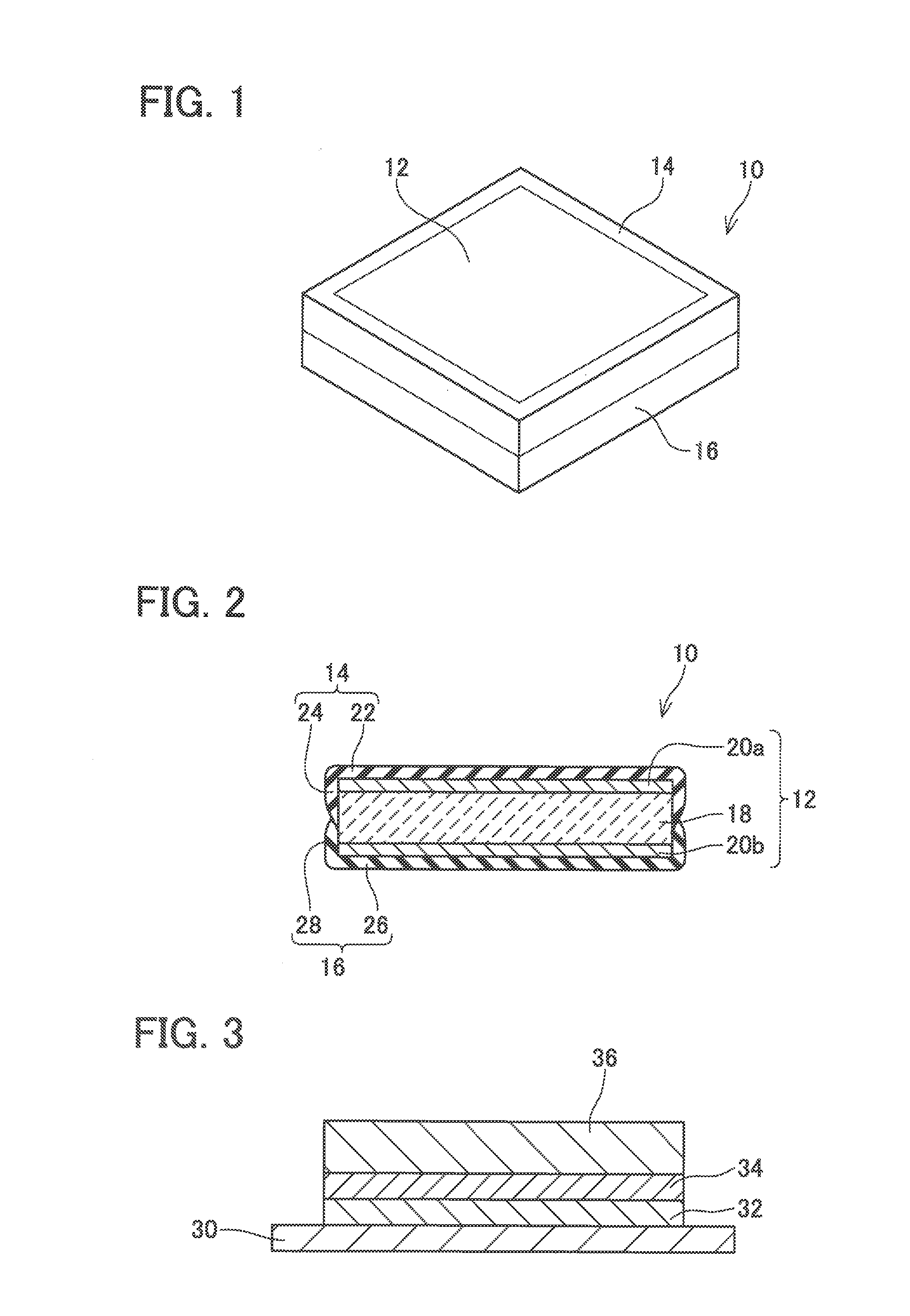
[0029]As shown in FIG. 1, a piezoelectric element 10 according to the first embodiment is an example of a ceramic element, and comprises a piezoelectric body 12 and resin coating layers 14 and 16. The resin coating layer 14 covers a portion of the front surface and a portion of the side surface of the piezoelectric body 12. And the resin coating layer 16 covers a portion of the back surface and a portion of the side surface of the piezoelectric body 12. The entire side surface of the piezoelectric body 12 is covered over by the combination of the resin coating layers 14 and 16. Since the side surface of the piezoelectric body 12 is covered over by the combination of the two resin coating layers 14 and 16, accordingly the boundary between the two resin coating layers 14 and 16 runs along an intermediate portion of the side surface of the piezoelectric body 12.

[0030]As shown in FIG. 2, the piezoelectric body 12 comprises a piezoelectric layer 18 and surface electrodes 20a and 20b that...

second embodiment

[0050]With a piezoelectric element of a second embodiment, the feature that the entire side surface of the piezoelectric body 12 and a portion of the back surface of the piezoelectric body 12 are covered over by the resin coating layer 62 that covers the front surface of the piezoelectric body 12, is different from the case of the first embodiment. Since the other structures are similar to ones of the piezoelectric element 10 of the first embodiment, accordingly explanation thereof will be omitted. Moreover, to elements and structures that are the same as ones of the piezoelectric element 10 of the first embodiment, the same reference symbols will be appended.

[0051]As shown in FIG. 10, with this piezoelectric element 60 of the second embodiment, the resin coating layer 62 extends continuously from the front surface of the piezoelectric body 12 over its side surface, and from its side surface onto its bottom surface. The resin coating layer 62 includes a front surface covering portio...


PUM


Abstract

A ceramic element includes: a ceramic body; a first coating layer disposed on a first part of a front surface of the ceramic body; and a second coating layer disposed on a second part of a back surface of the ceramic body. The first coating layer continuously extends from the front surface to a first region of a side surface of the ceramic body, the side surface being a machined surface, and the first region being a front side region of the side surface. The second coating layer continuously extends from the back surface to a second region of the side surface of the ceramic body, the second region being a back side region of the side surface. In the machined surface, one of the first and second coating layers is disposed at least partially on the other of the first and second coating layers.

Description

CROSS-REFERENCE TO RELATED APPLICATION[0001]This application claims priority to Japanese Patent Application No. 2013-7145 filed on Jan. 18, 2013, the contents of which are hereby incorporated by reference into the present application.TECHNICAL FIELD[0002]The present teachings relate to a ceramic element that includes a ceramic body, and to a method of manufacturing the same.DESCRIPTION OF RELATED ART[0003]A method is publicly known for manufacturing a ceramic element (for example, a piezoelectric element or the like) by mechanical processing of a ceramic wafer (for example, by dicing or the like). With this type of ceramic element, there is a problem that ceramic particles can easily be dropped off from the machined surface of the ceramic body. Due to this, a technique has been developed for suppressing dropping of ceramic particles by coating the machined surface of the ceramic body with a coating layer (for example, refer to Japanese Patent Application Publication No. 2011-514608)...

Claims


Application Information

Patent Timeline
IPC IPC(8): C04B41/81H01L41/331
CPCH01L41/331C04B41/81Y10T156/1082Y10T428/239Y10T428/23Y10T428/232H10N30/883H10N30/02H10N30/088H10N30/081H10N30/50H10N30/057H10N30/853
Inventor UETANI, MASAYUKIHATTORI, MASAKI
Owner NGK INSULATORS LTD
Why Eureka
Try Eureka