
Curtain gas filter for mass- and mobility-analyzers that excludes ion-source gases and ions of high mobility

Active Publication Date: 2011-07-21
SHIMADZU CORP
View PDF22 Cites 21 Cited by
  • Summary
  • Abstract
  • Description
  • Claims
  • Application Information

AI Technical Summary

Benefits of technology

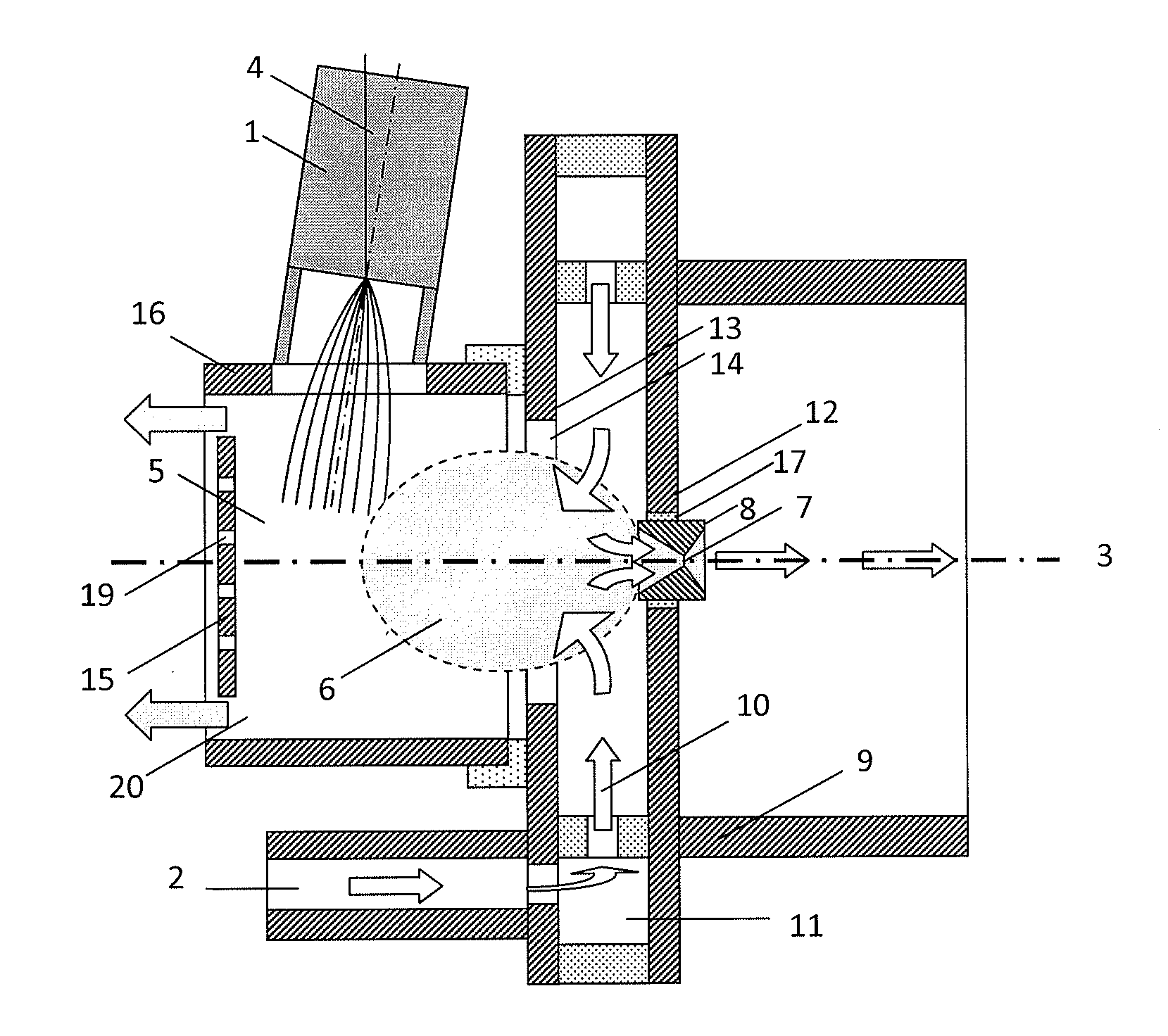
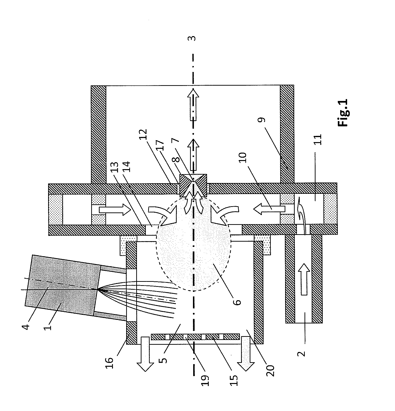
[0009]Guiding the effluent of a gas- or liquid-chromatograph into an atmospheric pressure ion source (API), the total ion current consists of the ionized molecules in this effluent as well as protonated water and solvent clusters. Since these cluster ions all have very high mobilities, the proposed curtain gas filter can eliminate them efficiently so that the total ion current registered in a detector placed downstream of this filter is a direct measure of the molecule flux in the effluent of these gas or liquid chromatographs. In all cases the ions—together with a buffer gas—are sucked through the aperture of a diaphragm or of a capillary or of the apertures of a multitude of diaphragms and / or capillaries into an evacuated mass analyzer or a lower pressure mobility analyzer. However, providing the ion-source buffer gas, in which the ions of interest are embedded, to a larger volume, one finds that gas-flow forces, which push neutral and ionized molecules or atoms into the evacuated mass spectrometer or lower-pressure mobility analyzer, are only effective within a much smaller “extraction volume” directly upstream of the aperture of a diaphragm or of a capillary or upstream of the apertures of a multitude of diaphragms and / or capillaries. If this “extraction volume” is filled by a separately supplied clean curtain gas, the ion-source buffer gas as well as the embedded ions can not enter the mass- or mobility-analyzer unless the filter according to the present invention provides electric fields that inject ions of interest into this “extraction volume”, with these ions being extracted from the ion-source buffer gas that surrounds the extraction volume.
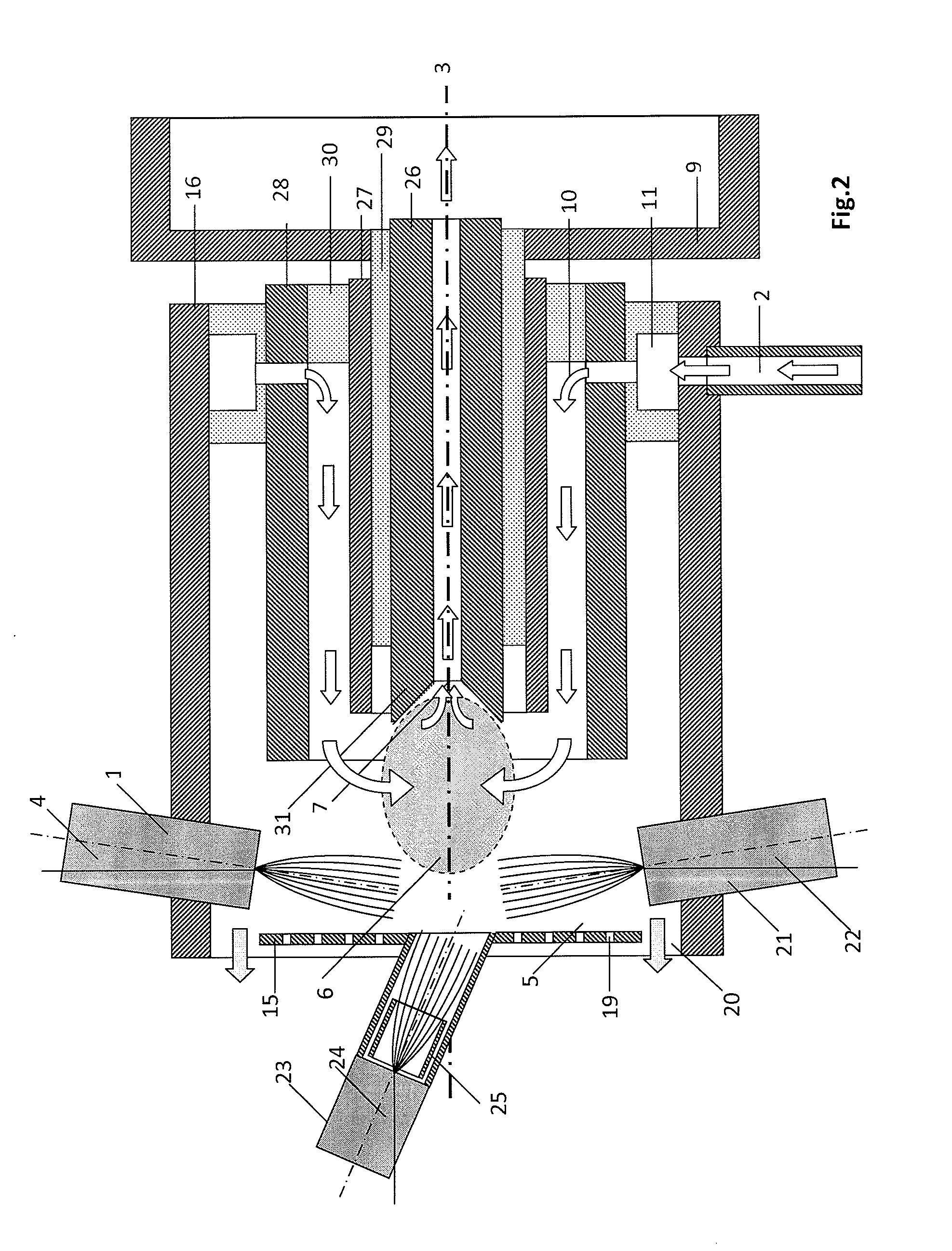
[0021]According to this embodiment the threshold mobility is adjusted by varying the magnitude of the mentioned high frequency field between the two substantially coaxial ion source gas guiding tubes, or the magnitude of the ion attracting potential applied to the mentioned tube placed around the passage, or the magnitude of the ion repelling potential of the mentioned at least one plate or at least one grid placed substantially perpendicular to the axis of ion extraction on the relative to the passage opposite side of the extraction volume. In this way this threshold mobility may be adjusted so that substantially only ions of high mobility formed from protonated clusters of water and solvent molecules are substantially eliminated. In this case only molecule ions of interest remain in the extraction volume and the total ion current downstream of the curtain gas filter monitors the content of molecule ions in the ion-source buffer gas, thus monitoring the content of molecules in the effluent of a gas- or liquid-chromatograph as a function of time. Entering these ions of interest downstream of the curtain-gas filter into a mass- or mobility spectrometer one may also avoid saturation effects in these spectrometers.

Problems solved by technology

However, providing the ion-source buffer gas, in which the ions of interest are embedded, to a larger volume, one finds that gas-flow forces, which push neutral and ionized molecules or atoms into the evacuated mass spectrometer or lower-pressure mobility analyzer, are only effective within a much smaller “extraction volume” directly upstream of the aperture of a diaphragm or of a capillary or upstream of the apertures of a multitude of diaphragms and / or capillaries.
Further, the electric fields are shaped such that undesired high mobility ions, as well as undesolvated droplets, when an electro-spray ion source is used, are guided not into but around the extraction volume, thus causing these ions to not enter the mass- or mobility-analyzer.

Method used


Image

  • Curtain gas filter for mass- and mobility-analyzers that excludes ion-source gases and ions of high mobility
  • Curtain gas filter for mass- and mobility-analyzers that excludes ion-source gases and ions of high mobility
  • Curtain gas filter for mass- and mobility-analyzers that excludes ion-source gases and ions of high mobility

Examples


Embodiment Construction

[0040]Exemplary embodiments will be described in greater detail with reference to the accompanying drawings. In the following description, the same drawing reference numerals are used for the same elements in all drawings. The matters defined in the description such as a detailed construction and arrangement of elements are only those provided to assist in a comprehensive understanding of the invention. Thus, it is apparent that the present invention can be carried out without being limited to those defined matters. Also, well-known functions or constructions are not described in detail since they would obscure the invention in unnecessary detail.

[0041]FIG. 1 is a schematic view of a first exemplary, non-limiting embodiment of a “filter for mass- and mobility-analyzers” that substantially eliminates ion-source gases and vapors as well as molecules of high mobilities. Except for the ion source 1 and the clean-gas inlet 2, this exemplary embodiment includes substantially rotational pa...


PUM


Abstract

A filter for a mass- or mobility-spectrometer that bars gases or vapors of a high-pressure ion source, as well as ions of high mobility and charged droplets, from entering an evacuated mass spectrometer or a mobility spectrometer at a lower pressure than the filter. The buffer gas of the high pressure ion source is blown into the volume of this filter directly or through tubes from where buffer gas and embedded ions are sucked through the aperture of a diaphragm or through an aperture of a capillary mainly from an “extraction volume” filled with a separately supplied clean gas, into which ions of interest are pushed by electric fields formed by electrodes that are substantially rotational symmetric around the “extraction volume” and a substantially flat electrode with respect to an axis of ion extraction and the end of the capillary and the end of a coaxial tube surrounding the capillary.

Description

[0001]This application claims the benefit of U.S. provisional application No. 61 / 103,168, filed Oct. 6, 2008, the entire disclosure of which is expressly incorporated herein by reference.BACKGROUND OF THE INVENTION[0002]1. Technical Field[0003]Aspects of the present invention relate to mass spectrometers, to mobility spectrometers, and to ion sources at elevated pressures such as atmospheric-pressure sources, and more specifically, to a curtain gas filter therefor.[0004]2. Related Art[0005]For related art investigations of large molecules, mass spectrometers and mobility spectrometers may be used. The mass spectrometers investigate the total molecule weight, which is approximately proportional to the volume of the molecule under investigation. The mobility spectrometer investigates the speed of a charged molecule when dragged through a buffer gas, a quantity which is approximately proportional to the cross section of the molecule under investigation.[0006]For both related art system...

Claims


Application Information

Patent Timeline
IPC IPC(8): H01J49/40H01J49/26
CPCH01J49/10H01J49/0422
Inventor WOLLNIK, HERMANNTARASSOV, ALEXANDEREICEMAN, GARY A.
Owner SHIMADZU CORP
Learn More