Implantable medical device depth estimation

a medical device and depth estimation technology, applied in the field can solve the problems of difficulty in powering such implantable medical devices, inconvenient replacement limited power supply of onboard batteries of implantable medical devices, so as to reduce compliance with charging procedures, affect communication efficiency, and prolong charging time

Active Publication Date: 2014-07-24
LIVANOVA USA INC
View PDF18 Cites 27 Cited by
  • Summary
  • Abstract
  • Description
  • Claims
  • Application Information

AI Technical Summary

Benefits of technology

[0004]Charging inefficiencies of an implantable medical device may reduce compliance with a charging procedure, may lead to longer charging time, or both. Factors associated with such charging inefficiencies may also affect communication efficiency between the implantable medical device and an external device (e.g., an external charging device or an external programming device). Systems and methods described herein may improve charging efficiency of an implantable medical device, may improve communication efficiency between the implantable medical device and the external device, or may improve both charging efficiency and communication efficiency.

Problems solved by technology

Powering such implantable medical devices may be challenging.
An onboard battery of an implantable medical device may provide a limited amount of power due to a finite amount of energy that can be stored in the onboard battery.
Replacing a battery of the implantable medical device may be expensive and inconvenient.
However, charging a rechargeable battery of an implantable medical device may present other challenges.
Charging inefficiencies may result in long charging times that may be undesirable for patients and may reduce compliance with a charging procedure.
Charging inefficiencies of an implantable medical device may reduce compliance with a charging procedure, may lead to longer charging time, or both.
In this embodiment, when the primary coil 124 is too far from or too close to the secondary coil 104, charging efficiency may be reduced, which may lead to increased heating of the implantable medical device 102 due to resistive losses, increased charging times, or both.
Since muscle and fat have different impedance values and since the settings of the tunable matching network may be pre-set based on the implant depth and based on an expectation that the implantable medical device 102 is implanted in fat, implantation of the implantable medical device 102 in muscle may cause an impedance mismatch.

Method used


Image

  • Implantable medical device depth estimation
  • Implantable medical device depth estimation
  • Implantable medical device depth estimation

Examples


Embodiment Construction

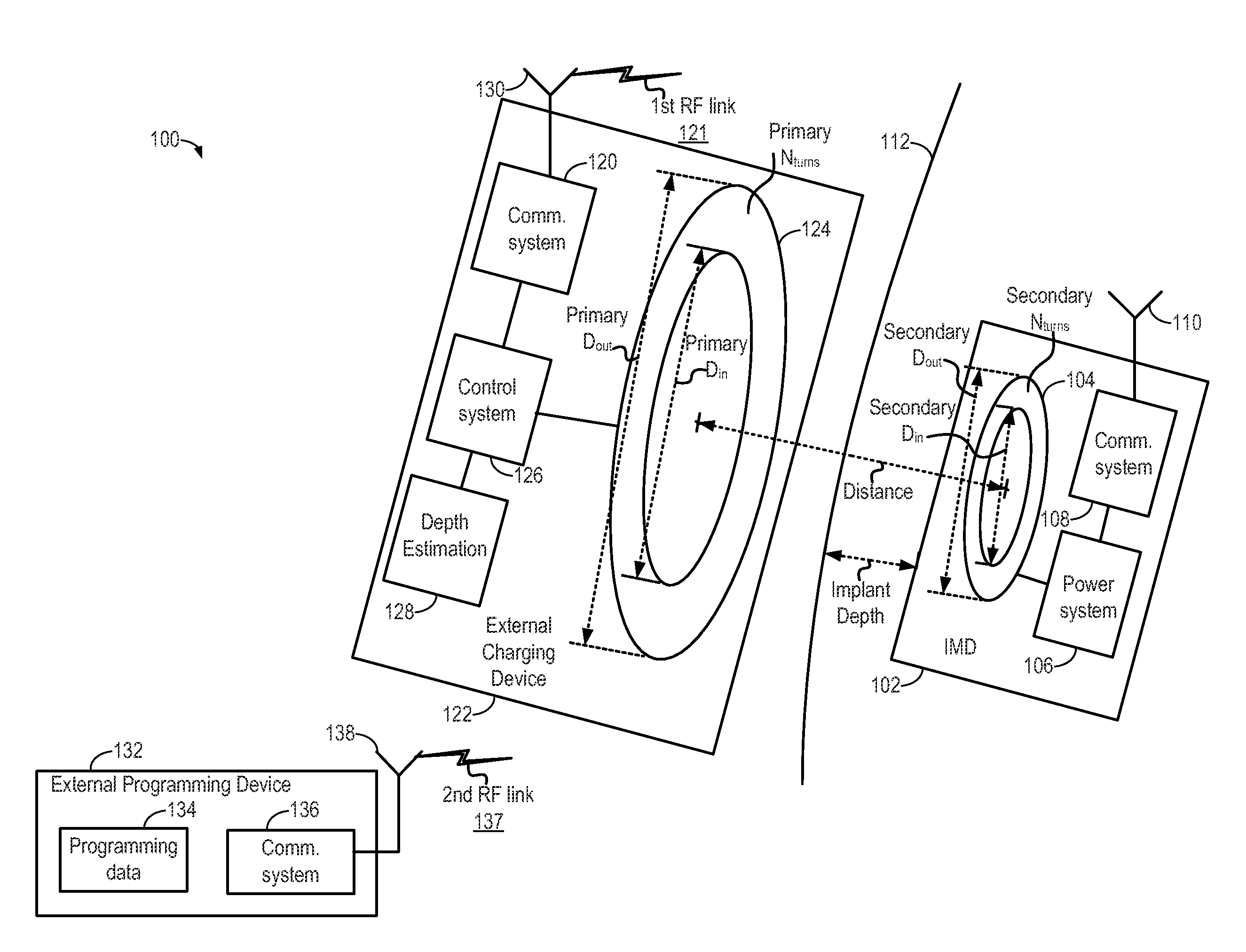
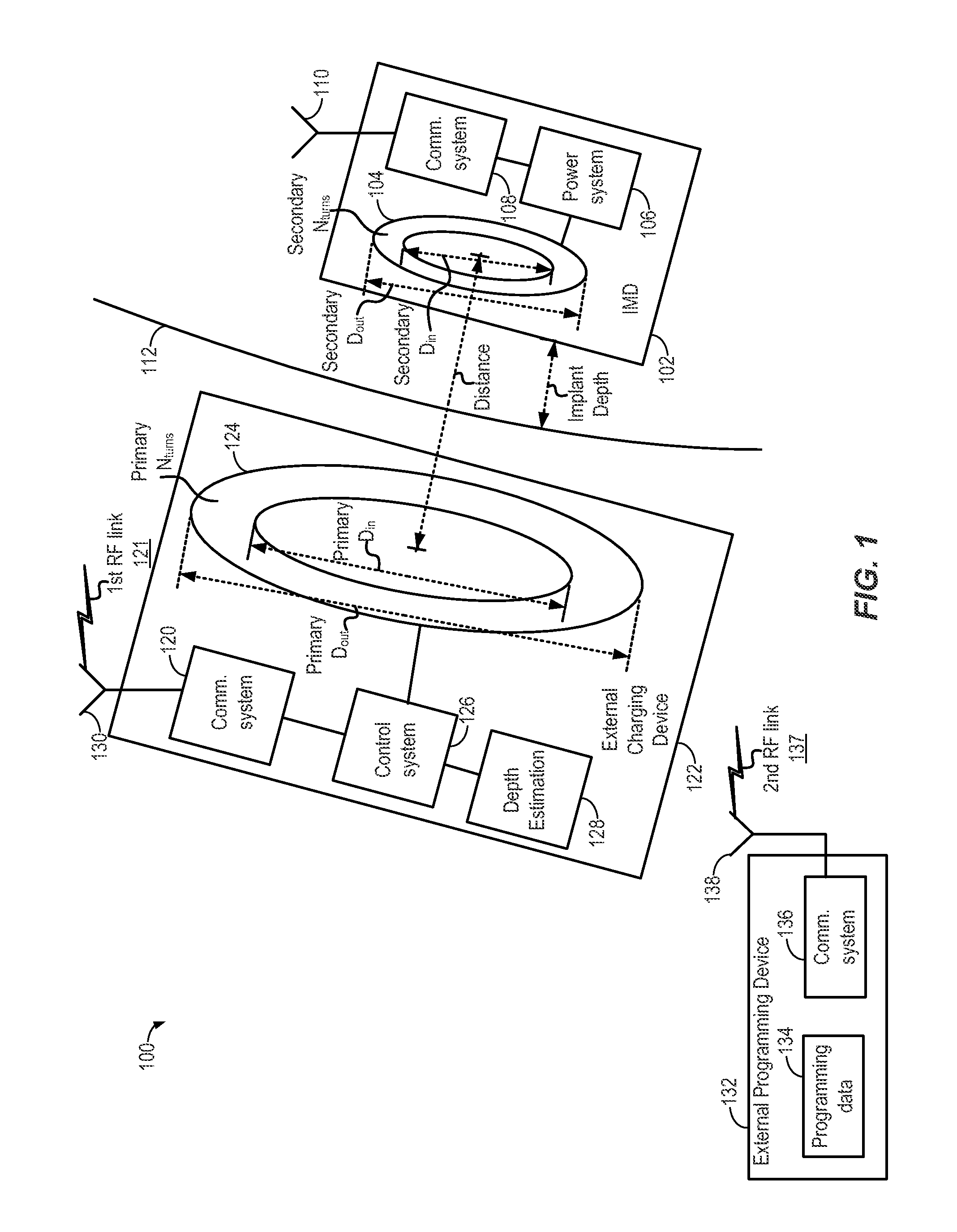
[0018]FIG. 1 is a block diagram of a first particular embodiment of a system 100 to estimate a depth of an implantable medical device 102 within tissue of a patient 112 during charging of the implantable medical device 102. For example, the implantable medical device 102 may be charged by an external charging device 122 via inductive coupling of a primary coil 124 of the external charging device 122 and a secondary coil 104 of the implantable medical device 102. Current induced at the secondary coil 104 may be rectified and applied to a battery of a power system 106 of the implantable medical device 102.

[0019]In a particular embodiment, the implantable medical device 102 includes a communication system 108. The communication system 108 may include one or more antennas, such as an antenna 110. The communication system 108 may be used to send information from the implantable medical device 102 via the antenna 110 and / or to receive information at the implantable medical device 102 via ...


PUM


Abstract

A method includes applying a signal to a primary coil of an external charging device. The signal causes the primary coil to inductively couple to a secondary coil of an implantable medical device that is implanted within tissue of a patient. The method also includes measuring a current at the primary coil. The method further includes estimating a depth of the implantable medical device within the tissue of the patient based on the measured current.

Description

FIELD OF THE DISCLOSURE[0001]The present disclosure is generally related to implantable medical devices.BACKGROUND[0002]Advances in technology have led to the development of small medical devices that can be implanted within a living organism, such as a human, to provide treatment or monitoring. Powering such implantable medical devices may be challenging. An onboard battery of an implantable medical device may provide a limited amount of power due to a finite amount of energy that can be stored in the onboard battery. Replacing a battery of the implantable medical device may be expensive and inconvenient. For example, invasive surgery may be needed to replace the battery of the implantable medical device after it is implanted in a patient. Due to these and other concerns, some implantable medical devices may use rechargeable batteries.[0003]However, charging a rechargeable battery of an implantable medical device may present other challenges. Charging inefficiencies may result in l...

Claims


Application Information

Patent Timeline
Patent Type & Authority Applications(United States)
IPC IPC(8): G01R19/00
CPCG01R19/0092A61N1/3787A61N1/37223
Inventor JOSHI, HIMANSHU
Owner LIVANOVA USA INC
Why Eureka
Try Eureka