Load Balanced Routing for Low Power and Lossy Networks

Inactive Publication Date: 2014-07-24
MITSUBISHI ELECTRIC RES LAB INC
View PDF8 Cites 194 Cited by
  • Summary
  • Abstract
  • Description
  • Claims
  • Application Information

AI Technical Summary

Benefits of technology

[0021]A node can record the time of receiving a route discovery packet from each potential parent nodes. An earlier time indicates that route discovery packet transmitter has

Problems solved by technology

The communication links between the nodes can be characterized by high loss rate, low data rate, instability, low transmission power, and short transmission range.
LLN applications typically require uneven node deployment and a high packet delivery rate, which can result in uneven workload of the nodes, referred as load unbalanced routing.
Load unbalanced routing can result in packet loss by LLN nodes due to small buffer sizes.
Also, routing overhead can increase the workload of LLN nodes, and therefore can result in extra packet loss.
Unfortunately, the conventional routing methods are not designed f

Method used


Image

  • Load Balanced Routing for Low Power and Lossy Networks
  • Load Balanced Routing for Low Power and Lossy Networks
  • Load Balanced Routing for Low Power and Lossy Networks

Examples


Embodiment Construction

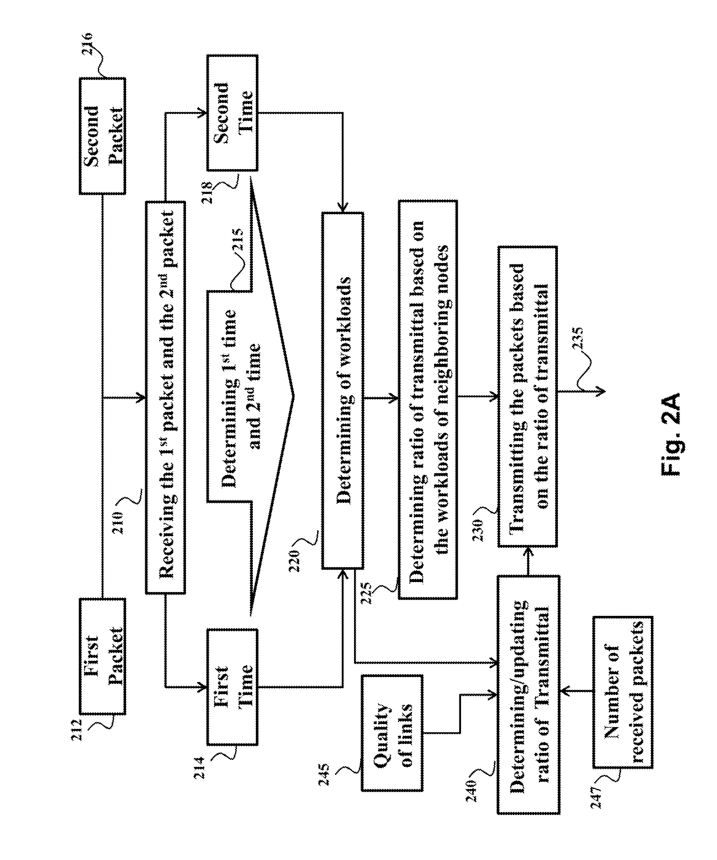
[0037]FIG. 2A shows a block diagram of a method for routing packets by a node 200 in a low-power and lossy network (LLN). FIG. 2B shows schematically a structure of the node 200. In various embodiments, the load balancing is achieved by transmitting the packets to the multiple nodes neighboring the node 200, e.g., at a rate proportional to the workloads of those neighboring nodes. Such transmittal allows balancing the load over multiple neighboring nodes, instead of transmitting all packets to a single parent node in an unbalanced manner. Moreover, the allocation of the packets transmitted to the neighboring nodes is based on current workloads of those nodes to balance the overall workload of the neighboring nodes. In various embodiments, the comparison of the workloads is performed without increasing communication overhead of the LLN.

[0038]For example, a first packet 212 is received 210 by the node 200 from a first node at a first time 214, and a second packet 216 is received 210 b...


PUM


Abstract

A node includes a receiver for receiving a first packet from a first node at a first time and a second packet from a second node at a second time, a processor for determining the first time and the second time and for comparing the first time with the second time to produce a ratio of workloads of the first node and the second node, and a transmitter for transmitting packets to the first and the second nodes based on the ratio.

Description

FIELD OF THE INVENTION[0001]This invention relates generally to routing packets in wireless networks, and particularly to load balanced routing for low power and lossy networks.BACKGROUND OF THE INVENTION[0002]In low-power and lossy networks (LLNs), nodes and communication links are constrained. Nodes in the LLN typically operate with resource constrains on processing power, memory, power consumption, lifetime, rate of activity, and physical size. The communication links between the nodes can be characterized by high loss rate, low data rate, instability, low transmission power, and short transmission range. There can be from a few dozen up to thousands of nodes within a practical LLN. Examples of LLN include a smart meter network, and a wireless sensor network for building monitoring.[0003]In contrast with other networks, the LLN can also have constrained traffic pattern. Multipoint-to-point, e.g., from nodes inside the LLN towards a central control or data concentrator node, traff...

Claims


Application Information

Patent Timeline
IPC IPC(8): H04W28/08H04W28/02
CPCH04W28/0236H04W28/08H04W40/04H04W40/12H04L45/24H04L45/26H04L43/0852H04L47/125Y02D30/70Y04S40/00
Inventor GUO, JIANLINLIU, XINXINBHATTI, GHULAMORLIK, PHILIPPARSONS, KIERAN
Owner MITSUBISHI ELECTRIC RES LAB INC
Why Eureka
Try Eureka