
Automated fresh air cooling system

a technology of automatic cooling and ventilation system, which is applied in ventilation system, lighting and heating apparatus, heating types, etc., can solve the problems of undesirable noise and vibrations that penetrate the occupied space of the building, the cooling capacity of whole house fans is limited, and the cost of traditional air conditioning system running is high and inefficien

Inactive Publication Date: 2014-07-24
QC MFG
View PDF18 Cites 35 Cited by
  • Summary
  • Abstract
  • Description
  • Claims
  • Application Information

AI Technical Summary

Benefits of technology

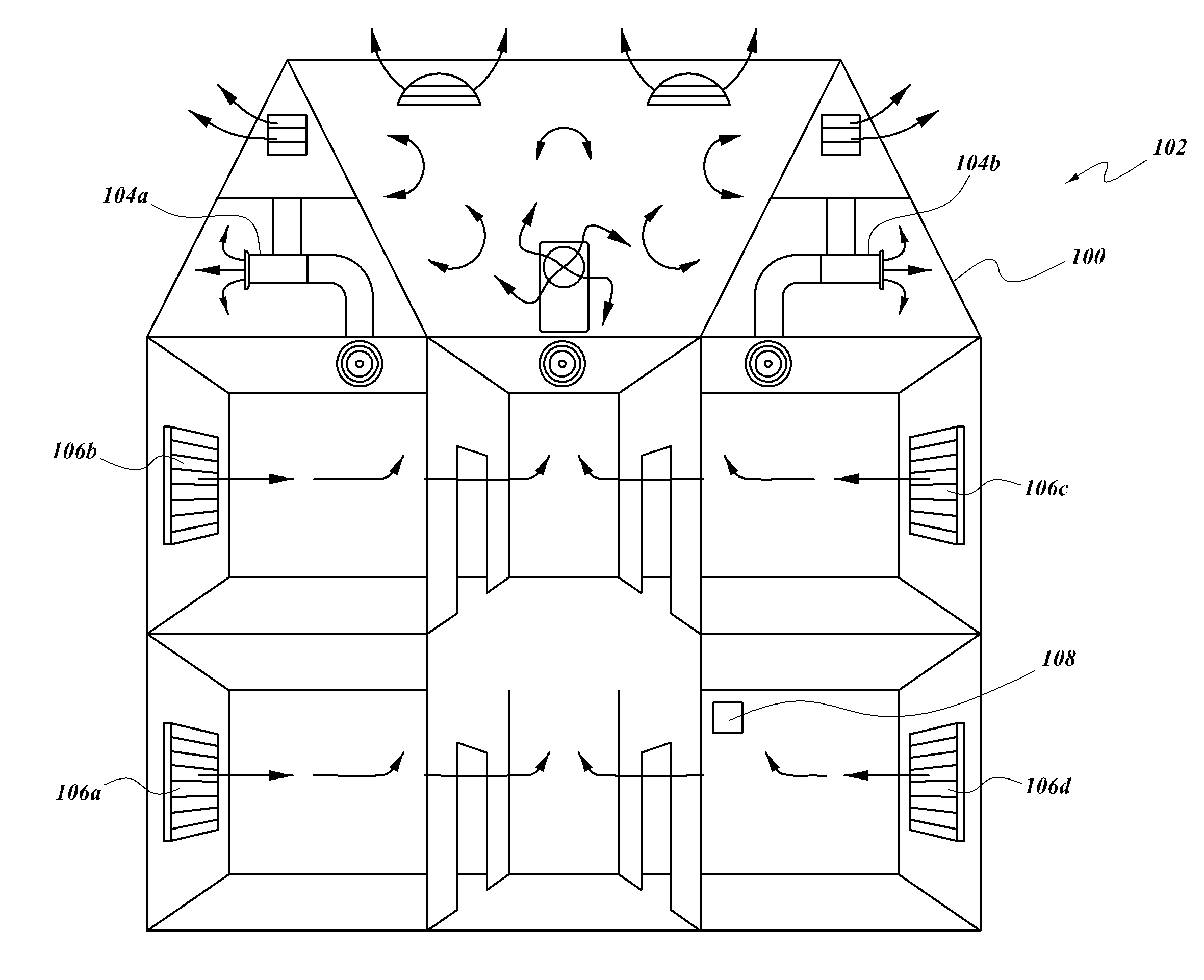
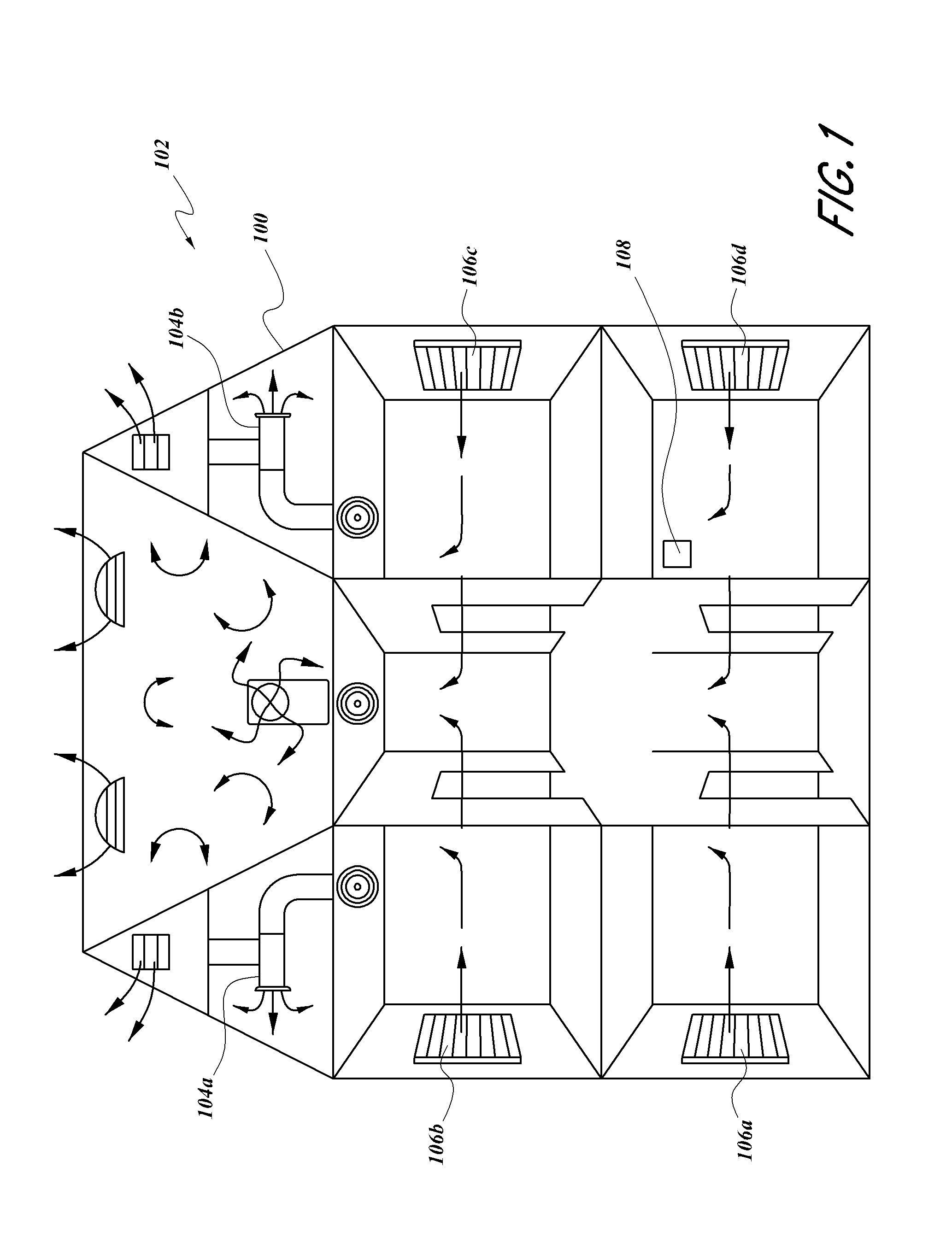
The patent describes an automated system for cooling buildings using a whole house fan and an air intake with vents and a motor. The system can also include an air conditioning system and internal temperature sensors. The programmable controller can automatically operate the air intake and fan based on external temperature measurements, and can also control the air conditioning system based on the temperature. The system can provide fresh air cooling without user input and can be retrofitted onto existing buildings. The technical effect is an efficient and effective way to cool buildings in a cost-effective and automated manner.

Problems solved by technology

It is well known that heating and cooling the space in residential and commercial buildings accounts for a primary share of building energy consumption.
While effective at conditioning the air, such traditional air conditioning systems are costly to run and are not energy efficient.
As such, the large capacity whole house fans, necessary to create sufficient negative pressure to draw the cooler air inside in the home, can create undesirable noise and vibrations that penetrate the occupied space of the building.
However, such whole house fans require open windows to serve as intake air vents.
Additionally, the cooling capabilities of whole house fans are limited by the ambient outside air.
Whole house fans are incapable of lowering the temperature and humidity of the air drawn into the building.
Accordingly, whole house fans are not effective at cooling the space when the outside ambient air temperature is higher than the internal air temperature.
Thus, a user operating the whole house fan under unsuitable conditions may actually heat the space when they intended to use the fan to cool the space.

Method used


Image

  • Automated fresh air cooling system
  • Automated fresh air cooling system
  • Automated fresh air cooling system

Examples


Embodiment Construction

[0024]Embodiments of the present disclosure provide for an automated fresh air cooling system. The fresh air cooling system can include an air intake system, a whole house fan, a vent system, an air conditioner, an integrated thermostat, and one or more temperature and / or humidity sensors.

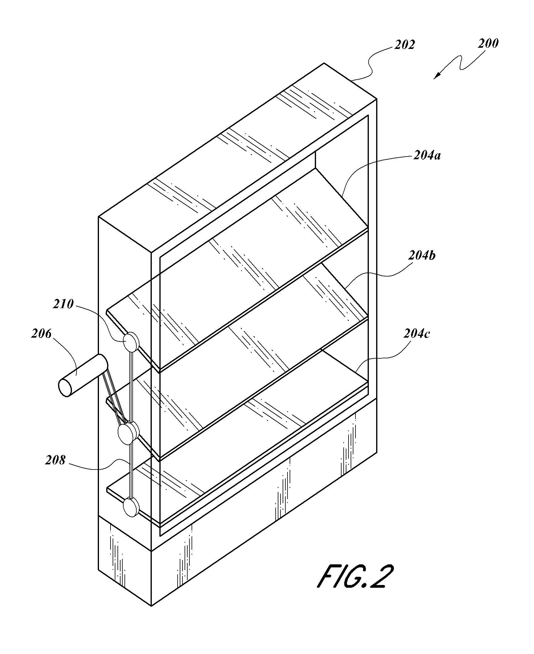
[0025]In some embodiments, the air intake system can include a motorized multi-bladed damper to automatically open and close whenever the thermostat detects optimal cooling conditions. The multi-bladed dampers can be fitted with an air filtration system to filter external pollutants. The integrated thermostat can control the fresh air cooling system by measuring internal and external conditions with internal and external temperature and / or humidity sensors. When the external temperature is at or below the internal temperature and the integrated thermostat is active, the thermostat can automatically open the air intake, the vent, and can turn on the whole house fan or fans. When the external tempera...


PUM


Abstract

Embodiments of the present disclosure are directed to an automated fresh air cooling system. The automated fresh air cooling system can include a whole house fan, an air intake, an air conditioner, and at least one controller. The controller can adjust the usage of the different components of the fresh air cooling system in order to reduce overall energy consumption as well as cost to a consumer. The system can be completely automated and no user input is required.

Description

BACKGROUND[0001]1. Field[0002]The present disclosure generally relates to automated cooling and ventilation systems for building structures, and more particularly, to the combination of a whole house fan system, an air intake system, an air conditioning system, and an integrated thermostat with interior and exterior building temperature sensors to reduce building energy consumption.[0003]2. Description of the Related Art[0004]It is well known that heating and cooling the space in residential and commercial buildings accounts for a primary share of building energy consumption. Space heating and cooling combined in residential buildings accounts for 54% of residential site energy consumption and 22% of total primary energy consumption in the U.S. See Table 2.1.5 2010 Residential Energy End-Use Splits, by Fuel Type in 2011 Buildings Energy Data Book, U.S. Department of Energy, March 2012, hereby incorporated by reference in its entirety.[0005]Existing buildings utilize either an air co...

Claims


Application Information

Patent Timeline
IPC IPC(8): F24F11/053F24F11/76
CPCF24F11/053F24F11/76
Inventor STEVENSON, DANA CHARLES
Owner QC MFG
Learn More