Harmonic drive

a technology of harmonic drive and drive shaft, which is applied in the direction of belt/chain/gearing, toothed gearing, belt/chain/gearing, etc., can solve the problems of complex and difficult manufacturing processes of flexible gears, and the harmonic drive of the prior art is vulnerable. , to achieve the effect of strong rigidity, high reduction ratio and invulnerability

Inactive Publication Date: 2014-07-24
HARMONIC INNOVATION TECH
View PDF9 Cites 3 Cited by
  • Summary
  • Abstract
  • Description
  • Claims
  • Application Information

AI Technical Summary

Benefits of technology

[0008]In contrast to the prior art, the harmonic drive of the present invention utilizes rigid gears to achieve a high reduction ratio, therefore, the harmonic drive of the present invention has stronger rigidity and is invulnerable. In addition, manufacturing processes of the rigid gears are simpler, thus the harmonic drive of the present invention is easy to manufacture with high yield rate. Moreover, a difference between a number of teeth of the first gear and a number of teeth of the second gear can be an odd number or an even number, therefore, the reduction ratio of the harmonic drive of the present invention has more flexibility.

Problems solved by technology

However, the harmonic drive of the prior art is vulnerable since the flexible gear is made of softer material, and manufacturing processes of the flexible gear are complex and difficult.

Method used


Image

  • Harmonic drive
  • Harmonic drive
  • Harmonic drive

Examples


Embodiment Construction

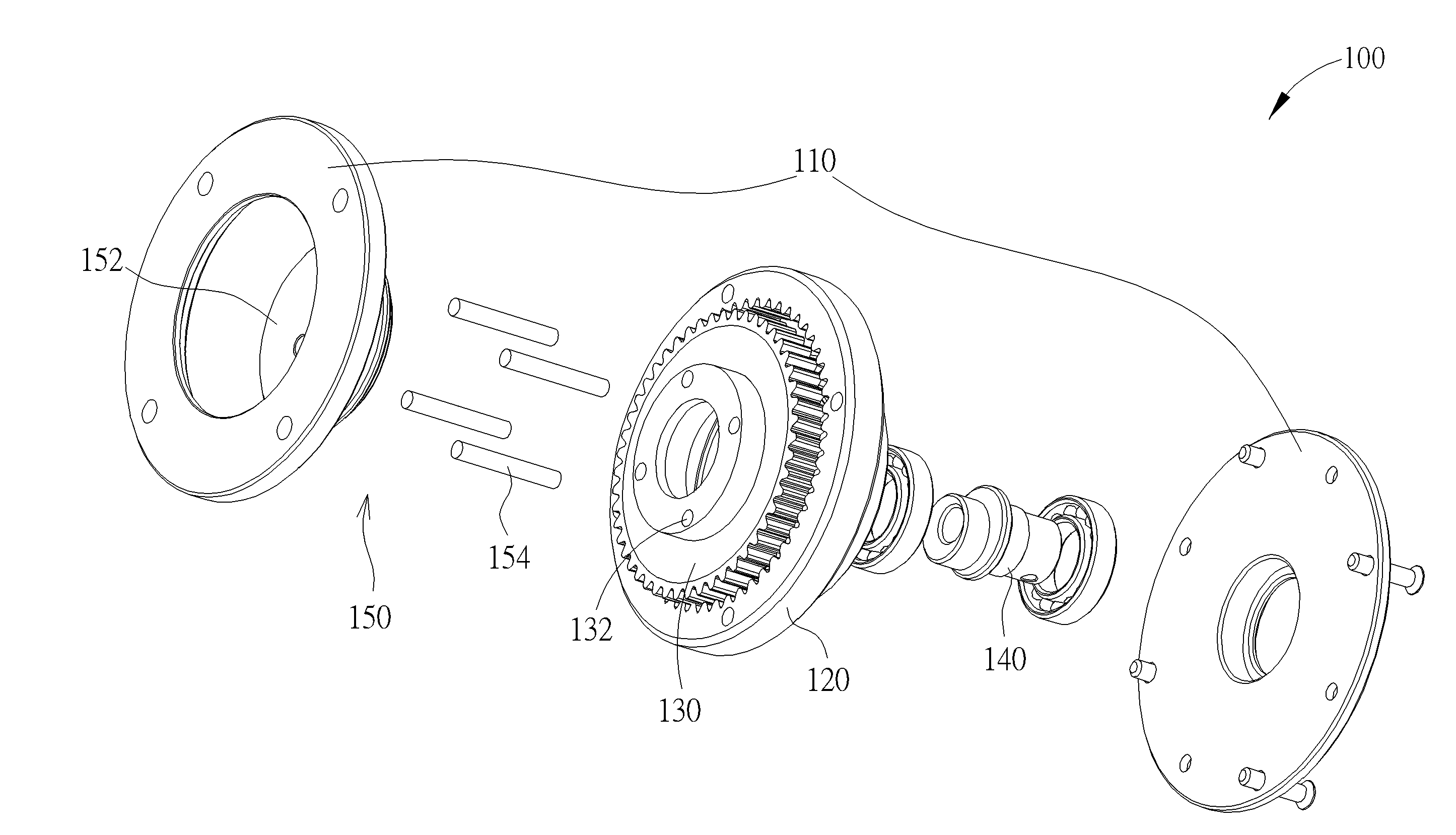
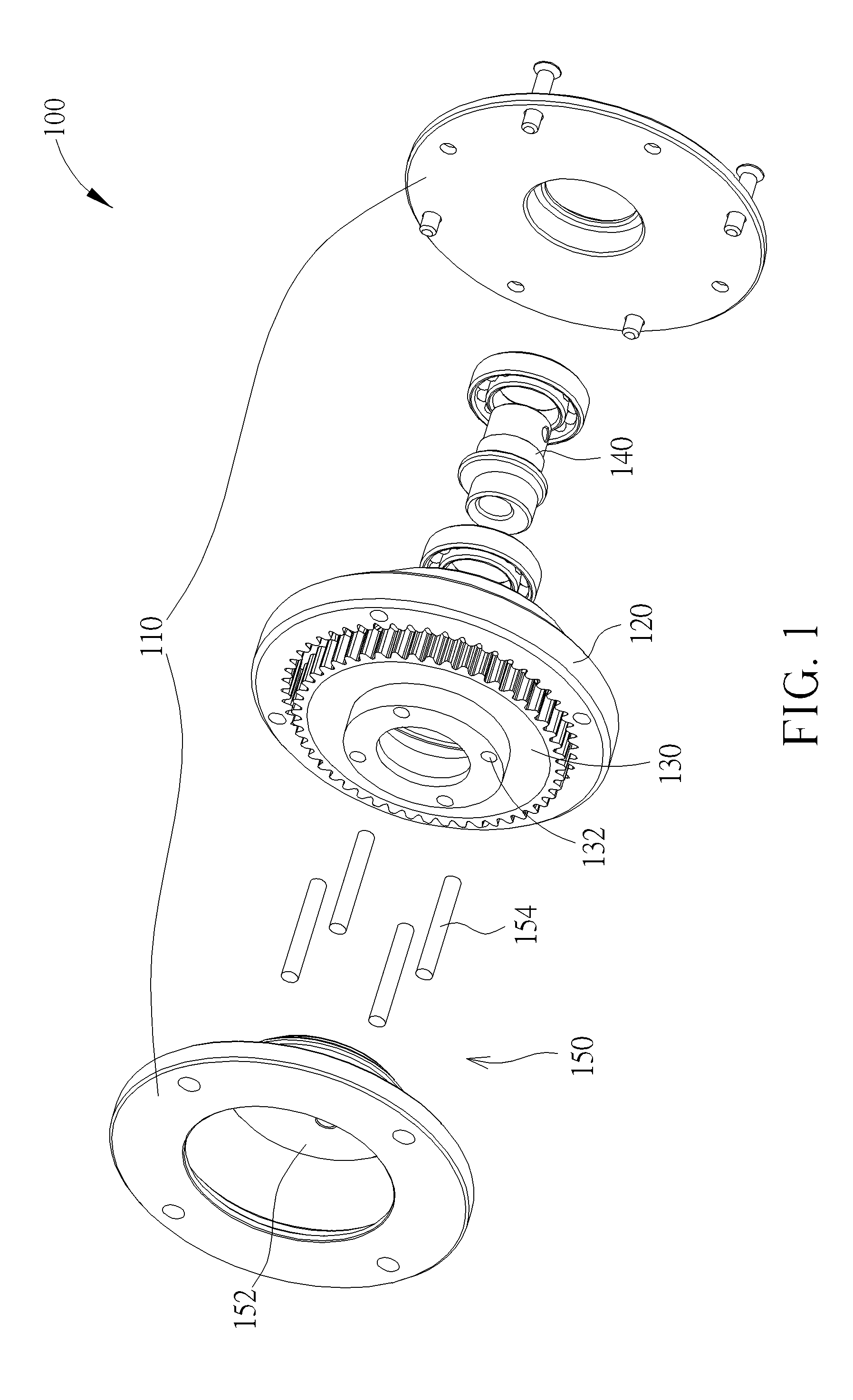
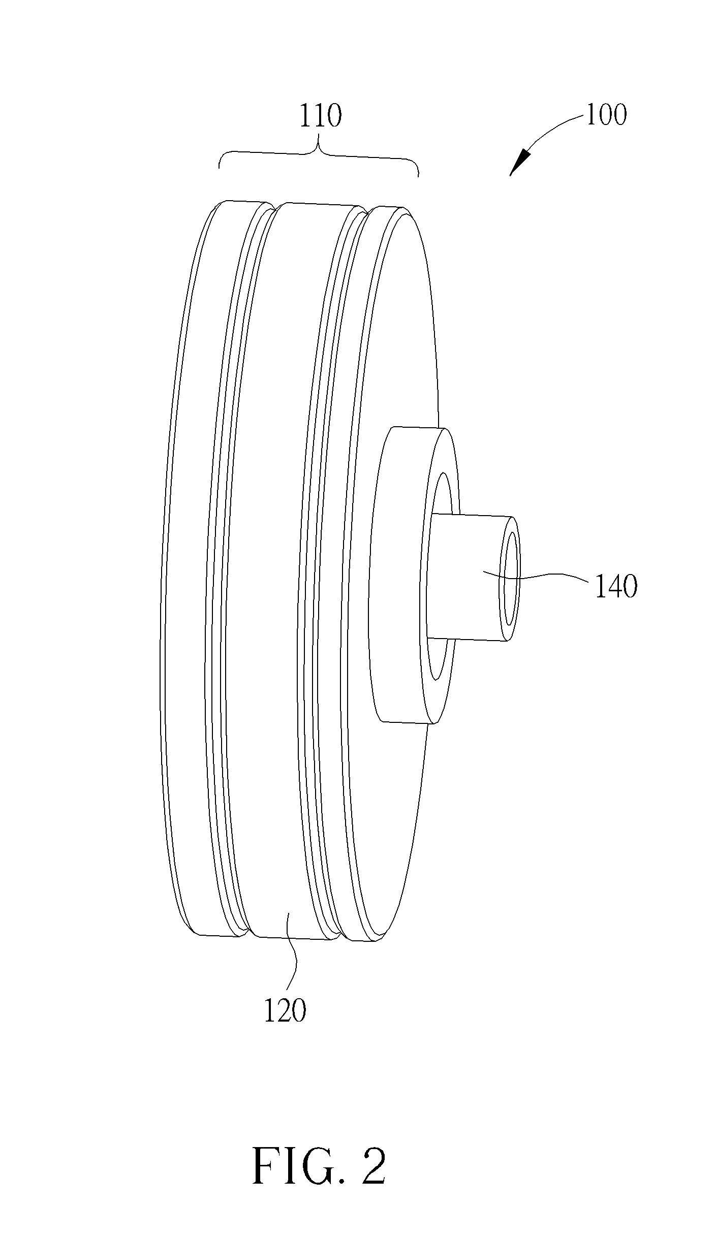
[0013]Please refer to FIG. 1 and FIG. 2. FIG. 1 is an exploded view diagram of a harmonic drive of the present invention. FIG. 2 is an assembly diagram of the harmonic drive of FIG. 1. As shown in figures, the harmonic drive 100 of the present invention comprises a housing 110, a first gear 120, a second gear 130, an eccentric shaft 140, and a power outputting unit 150. The first gear 120 is fixed to the housing 110, and has a first number of internal teeth. The second gear 130 is engaged with the first gear 120, and has a second number of external teeth. The second number is different from the first number. The eccentric shaft 140 is coupled to the second gear 130 for driving the second gear 130 to eccentrically rotate relative to the first gear 120. The power outputting unit 150 is coupled to the second gear 130 for converting eccentric rotation of the second gear 130 to rotary power. The power outputting unit 150 comprises a rotary unit 152, and a plurality of coupling units 154....


PUM


Abstract

A harmonic drive includes a housing, a first gear, a second gear, an eccentric shaft, and a power outputting unit. The first gear is fixed to the housing, and has a first number of internal teeth. The second gear is engaged with the first gear, and has a second number of external teeth. The second number is different from the first number. The eccentric shaft is coupled to the second gear for driving the second gear to eccentrically rotate relative to the first gear. The power outputting unit is coupled to the second gear for converting eccentric rotation of the second gear to rotary power.

Description

NOTICE OF COPYRIGHT[0001]A portion of the disclosure of this patent document contains material which is subject to copyright protection. The copyright owner has no objection to any reproduction by anyone of the patent disclosure, as it appears in the United States Patent and Trademark Office patent files or records, but otherwise reserves all copyright rights whatsoever.BACKGROUND OF THE PRESENT INVENTION[0002]1. Field of Invention[0003]The present invention relates to a harmonic drive, and more particularly, to a rigid and easy to manufacture harmonic drive.[0004]2. Description of Related Arts[0005]A harmonic drive is a deceleration device with a high reduction ratio. The conventional harmonic drive generally comprises a rigid gear, a flexible gear and a wave generator. The wave generator is coupled to a power source (such as a motor), and the flexible gear is coupled to a power output shaft for outputting power. A number of teeth of the rigid gear is different from a number of tee...

Claims


Application Information

Patent Timeline
Patent Type & Authority Applications(United States)
IPC IPC(8): F16H1/32
CPCF16H1/32
Inventor YEH, CHUN-SHEN
Owner HARMONIC INNOVATION TECH
Why Eureka
Try Eureka