Automatic floor sweeping and mopping device

Inactive Publication Date: 2014-07-31
LIN CHING CHI
View PDF2 Cites 33 Cited by
  • Summary
  • Abstract
  • Description
  • Claims
  • Application Information

AI Technical Summary

Benefits of technology

[0009]An object of the present invention is to provide an automatic floor sweeping and mopping device that can carry out floor sweeping and mopping simultaneously.
[0010]Another object of the present invention is to provide an automatic floor sweeping and mopping device that enables floor cleaning to be done in a more efficient manner and in a shorter time.
[0011]A third object of the present invention is to provide an automatic floor sweeping and mopping device that leaves no water on the floor after use and thus may be used for regular floors as well as carpets.
[0012]A fourth object of the present invention is to provide an automatic floor sweeping and mopping device that is able to carry a larger amount of water, thus allowing cleaning for a larger floor area without any need to add more water.
[0013]To reach the objects, the automatic floor sweeping and mopping device of the present invention is disclosed. The device of the present invention can carry out automatic floor sweeping and mopping simultaneously. The automatic floor sweeping and mopping device of the present invention comprises a main body, a rotational sweeping brush unit, a dust collecting unit, two rolling wheels, a mopping unit, a water spraying unit, a squeegee unit and a water storing tank. The rotational sweeping brush unit is disposed on the underside of the main body to sweep dusts off the floor. The dust collecting unit is disposed in front of the rotational sweeping brush unit. A suct

Problems solved by technology

The machine of sweeping type can only get rid of regular dusts and can not eliminate finer dusts.
A disadvantage of such machine is that there is often some dirty water remaining on the floor.
Another disadvantage is that dirty water often gets into the cr

Method used


Image

  • Automatic floor sweeping and mopping device
  • Automatic floor sweeping and mopping device
  • Automatic floor sweeping and mopping device

Examples


Embodiment Construction

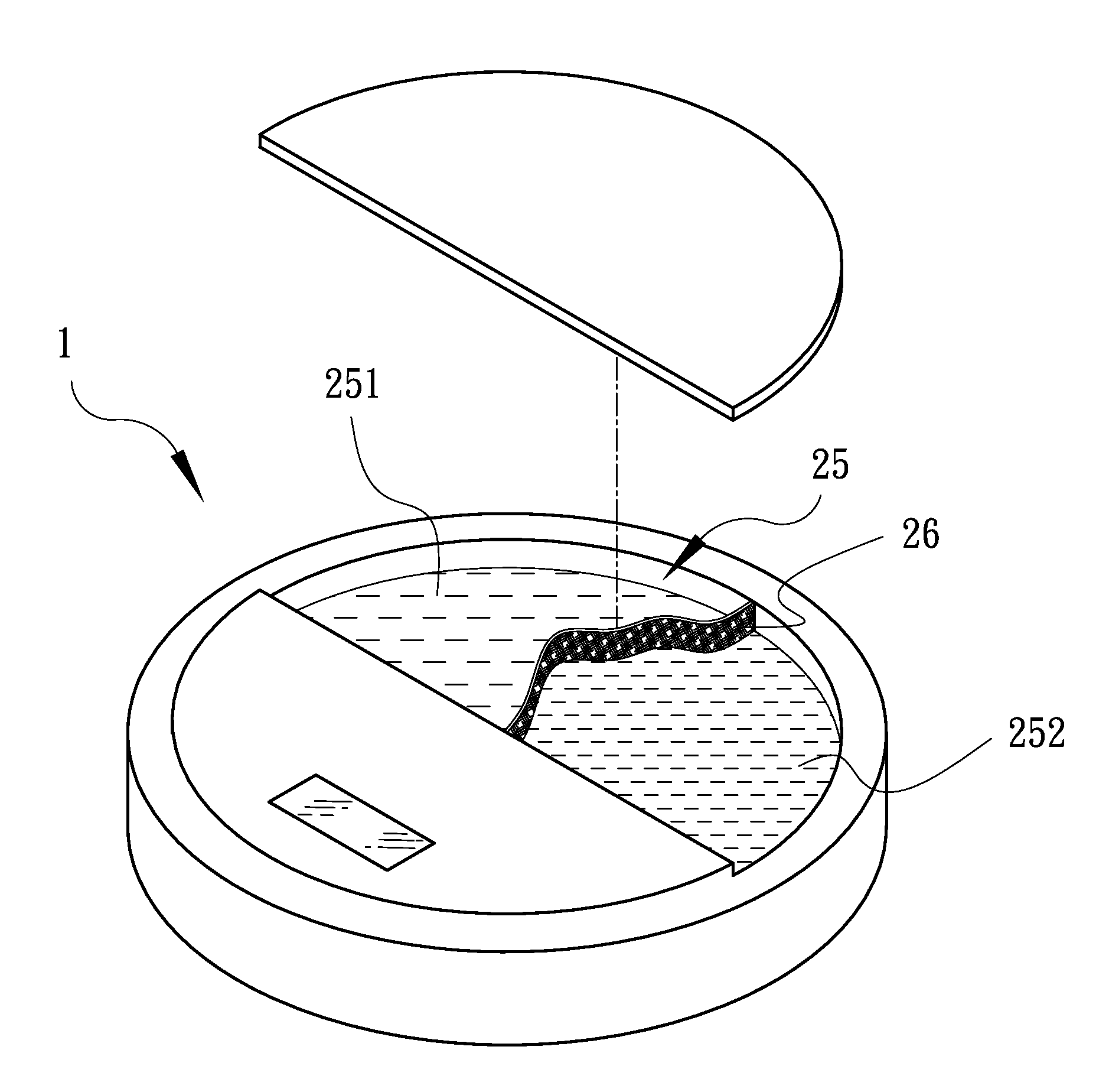
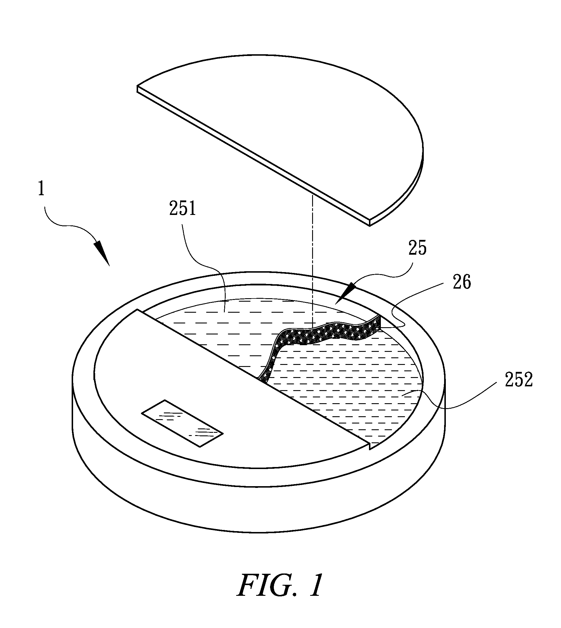
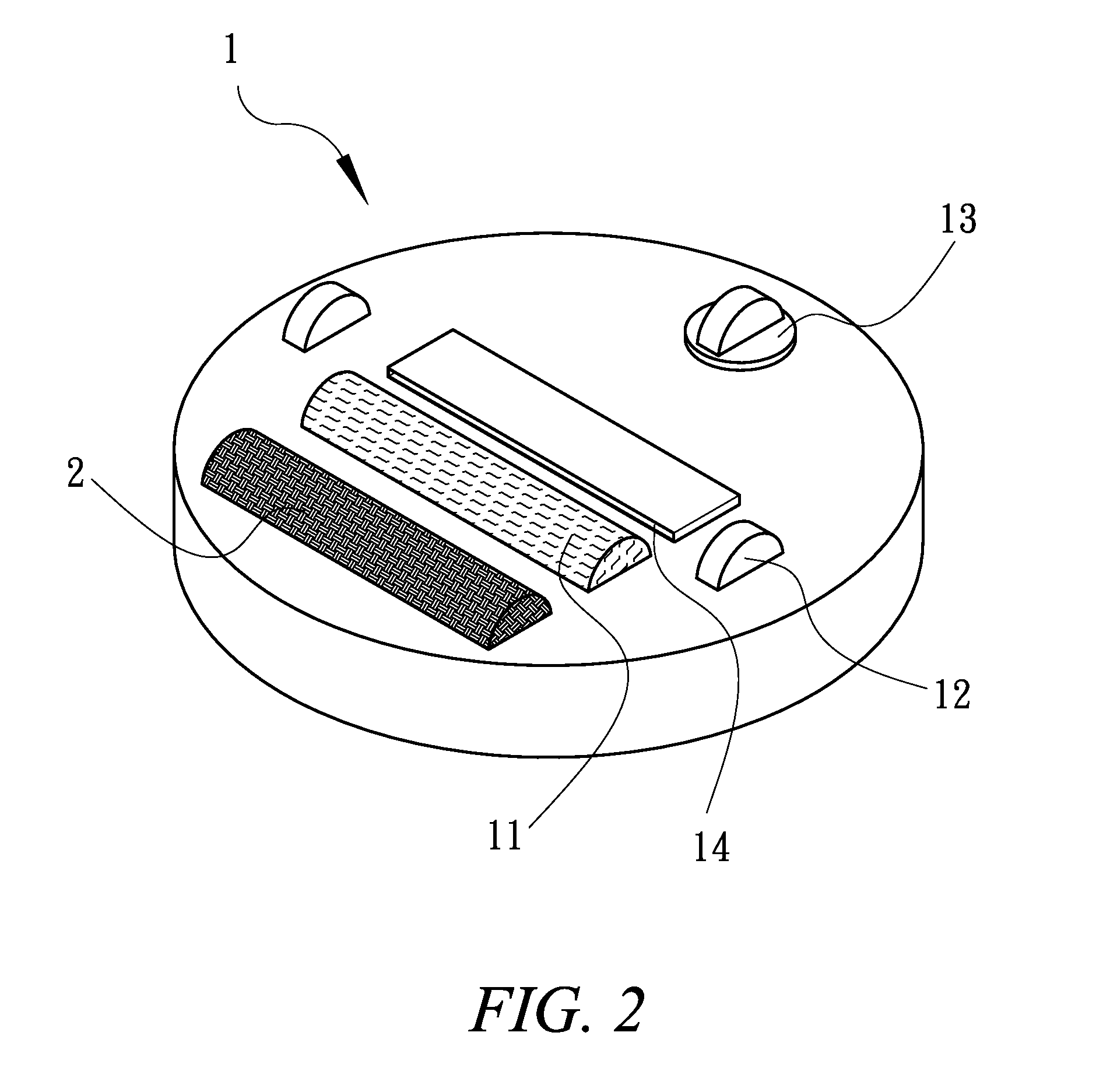
[0018]Please see FIGS. 1 and 4, which illustrate the automatic floor sweeping and mopping device of the present invention. The device of the present invention comprises a main body 1, a rotational sweeping brush unit 11, a dust collecting unit 14, two rolling wheels 12, a mopping unit 2, a water spraying unit 21, a squeegee unit 22 and a water storing tank 25. The rotational sweeping brush unit 11 is disposed on the underside of the main body 1 and the dust collecting unit 14 is disposed in front of the rotational sweeping brush unit 11. A suction fan (not shown in the drawings) is provided inside the dust collecting unit 14 to suck dusts into the dust collecting unit 14. One rolling wheel 12 is provided on either side of the dust collecting unit 14 and a turning wheel 13 is provided on the frontal portion on the underside of the main body 1. Therefore, the two rolling wheels 12 allow the forward and backward movements of the main body 1 and the turning wheel 13 allows the main body...


PUM


Abstract

The device of the present invention can carry out floor sweeping and mopping automatically and simultaneously. The automatic floor sweeping and mopping device includes a main body, a rotational sweeping brush unit, a dust collecting unit, two rolling wheels, a mopping unit, a water spraying unit, a squeegee unit and a water storing tank. The mopping unit is made of a soft, water-absorbing material and can remove residual dirt not removed by the rotational sweeping brush unit. The water spraying unit is an innovative feature and is provided above the mopping unit to keep the mopping unit in a clean condition by removing dusts and dirt stuck to it. The squeegee unit can squeeze dirt and dirty water out of the mopping unit and keep the mopping unit in a clean, partially wet condition. Because the device leaves no dirty water behind, such feature is surely superior.

Description

BACKGROUND OF THE INVENTION[0001]1. Field of the Invention[0002]The invention generally relates to a floor cleaning device. More particularly, the invention relates to an automatic floor cleaning device that can carry out floor sweeping (vacuuming) and mopping simultaneously. Thanks to its water spraying unit and squeegee unit, its mopping unit can be rinsed out to be kept in a clean, partially wet condition so that the device may be used to clean the floor in a continuous, efficient and easy manner.[0003]2. Description of the Prior Art[0004]As technology advances, the use of automated floor cleaning machines for floor cleaning has become quite common. In addition, such machines or robots may operate by themselves to clean the floor and thus eliminate human labor altogether.[0005]Such machines may be categorized into two types—sweeping type and mopping type. The machine of sweeping type can only get rid of regular dusts and can not eliminate finer dusts. Therefore, it needs a moppin...

Claims


Application Information

Patent Timeline
IPC IPC(8): A47L11/28
CPCA47L11/292A47L11/4088A47L11/4044A47L11/4041
Inventor LIN, CHING-CHI
Owner LIN CHING CHI
Why Eureka
Try Eureka