
Battery-powered handheld vacuum device

a handheld vacuum and battery technology, applied in the direction of motor fan assembly mounting, vacuum cleaners, domestic applications, etc., can solve the problem of relatively long length of the battery-operated handheld vacuum device, and achieve the effect of reducing dimensions

Active Publication Date: 2014-07-31
ROBERT BOSCH GMBH
View PDF12 Cites 56 Cited by
  • Summary
  • Abstract
  • Description
  • Claims
  • Application Information

AI Technical Summary

Benefits of technology

The present invention is about a new battery-powered vacuum device that is smaller and lighter. The technical effect of this invention is to offer a more portable and easy-to-use vacuum solution.

Problems solved by technology

The disadvantage of the related art is that the length of this battery-operated handheld vacuum device is relatively long due to the coaxial placement of the cup-shaped filters, fan impeller and drive motor.

Method used


Image

  • Battery-powered handheld vacuum device
  • Battery-powered handheld vacuum device
  • Battery-powered handheld vacuum device

Examples


Embodiment Construction

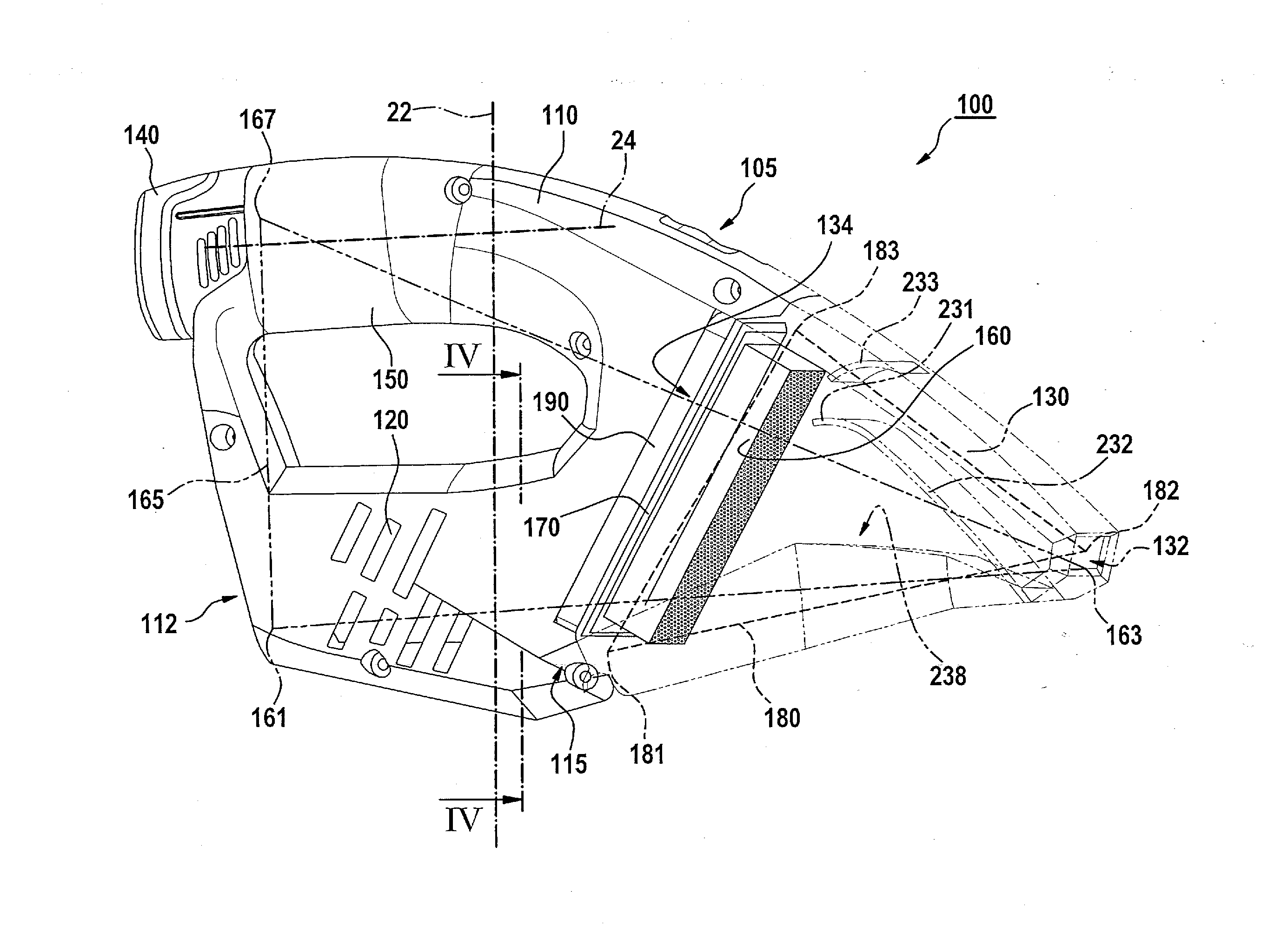
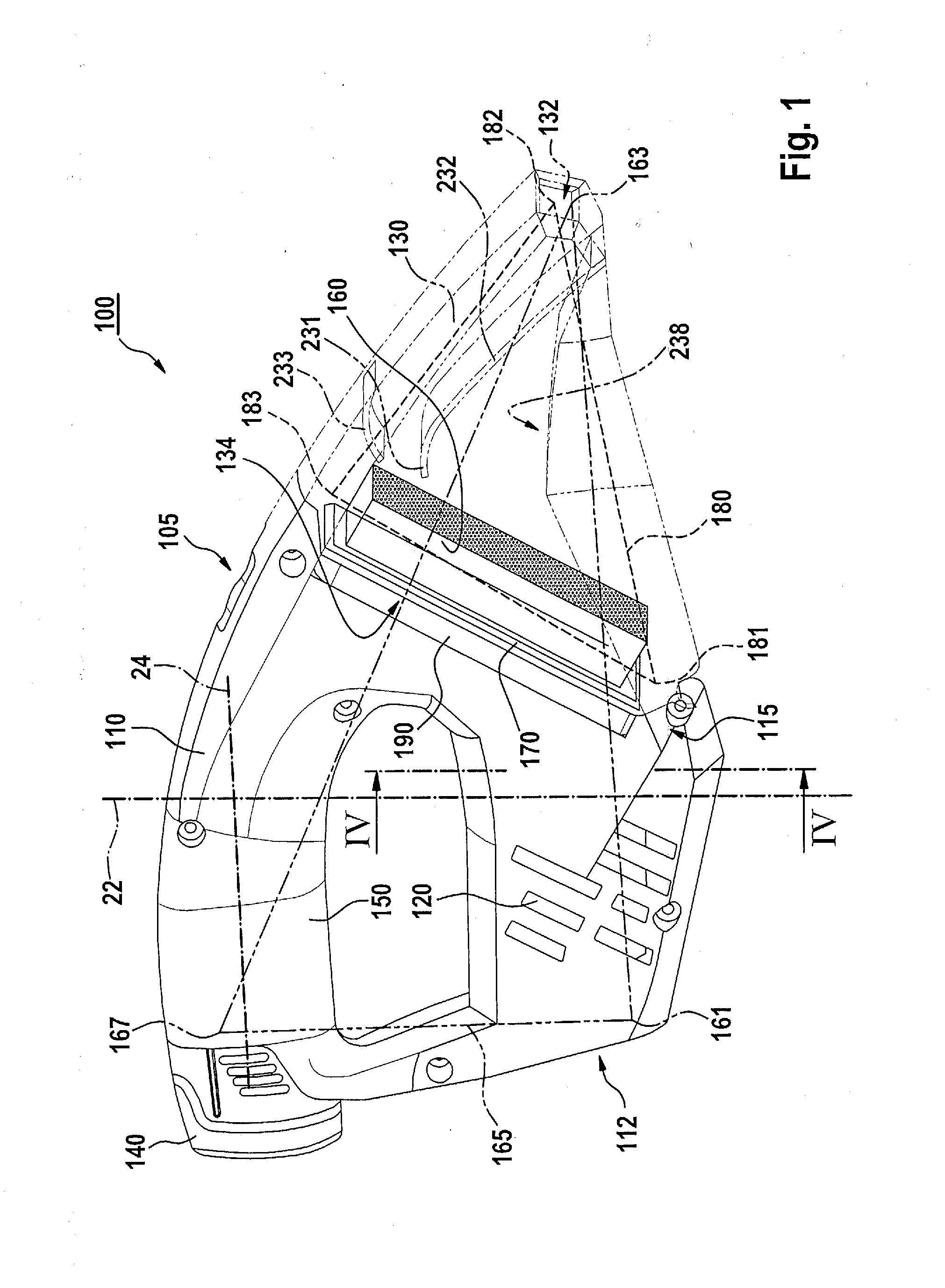
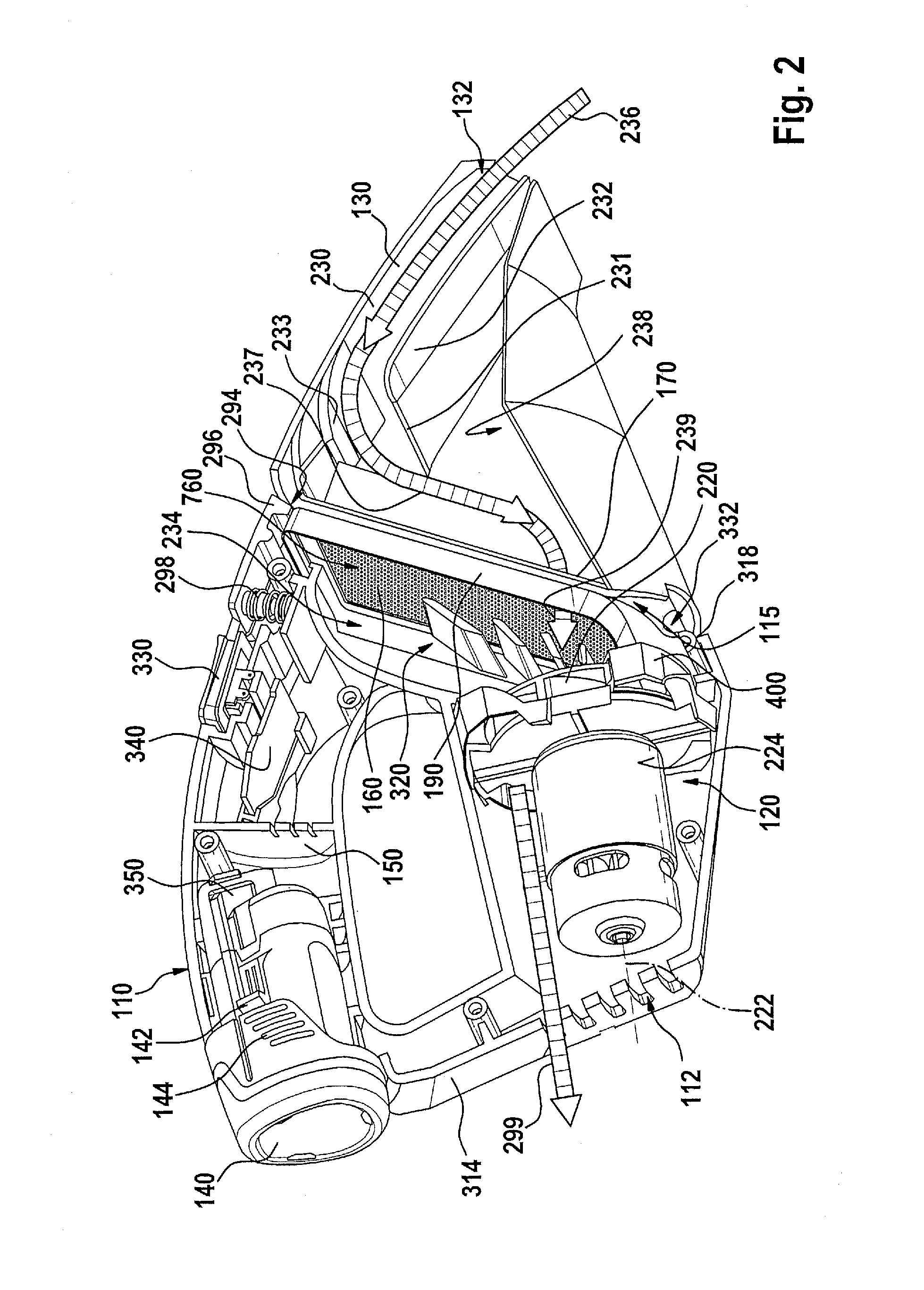
[0058]FIG. 1 shows a battery-powered handheld vacuum device 100 according to one specific embodiment, which is developed for use on building sites, in particular. It has a motor housing 110, on which a dust collection box 130 is fixed in place in a releasable manner. Disposed inside motor housing 110 are at least one drive motor 120 provided with a fan impeller (220 in FIG. 2), and a battery pack 140 for the current supply of drive motor 120 independently of an electrical network. Handheld vacuum device 100 may optionally include a charge state display for monitoring a corresponding charge state of battery pack 140.

[0059]Battery pack 140, for example, engages with motor housing 110 only regionally, as will be described below. Preferably, battery pack 140 has at least three battery cells (not shown further) and supplies a nominal voltage of 10.8V at an available capacity of 1.3 Ah, 1.5 Ah, 2.0 Ah or 4 Ah. Battery pack 140 has a battery pack housing, which is not further denoted here ...


PUM


Abstract

A battery-powered handheld vacuum device for use on building sites includes: a dust collection box; and a motor housing, in which a drive motor provided with a fan impeller and a battery pack for supplying current to the drive motor independently of an electrical network are provided. The dust collection box is fixed in place on the motor housing in releasable manner. A handle, with which the battery pack engages at least sectionally, is formed on the motor housing.

Description

BACKGROUND OF THE INVENTION[0001]1. Field of the Invention[0002]The present invention relates to a battery-powered handheld vacuum for use at building sites, which has a dust collection box and a motor housing; situated inside the motor housing are a drive motor equipped with a fan impeller and a battery pack to supply current to the drive motor independently of an electrical network, the dust collection box being mounted on the motor housing so as to be detachable.[0003]2. Description of Related Art[0004]A battery-powered handheld vacuum device of this type is known from published European patent application document EP 1 523 916 A2; it includes a dust collection box that is mounted on a motor housing in detachable manner; situated inside the motor housing are a drive motor equipped with a fan impeller and a battery pack for supplying current to the drive motor independently of an electrical network. A cup-shaped main filter is disposed inside the dust collection box; it is enclose...

Claims


Application Information

Patent Timeline
Patent Type & Authority Applications(United States)
IPC IPC(8): A47L5/24
CPCA47L5/24A47L9/122A47L9/22A47L9/2884
Inventor VISEL, BENJAMINROEHM, HEIKOMARGARITIS, GEORGIOS
Owner ROBERT BOSCH GMBH
Learn More