
Device for generating a gas jet in processes for coating metal strips

a technology of gas flow and metal strip, which is applied in the direction of metal material coating process, coating, hot-dipping/immersion process, etc., can solve the problems of significant increase in the turbulence of the device, major limit, and considerable increase in the load loss of the device, so as to improve the uniformity of the gas distribution

Active Publication Date: 2014-07-31
DANIELI & C OFF MEC SPA
View PDF1 Cites 0 Cited by
  • Summary
  • Abstract
  • Description
  • Claims
  • Application Information

AI Technical Summary

Benefits of technology

The present invention provides a device to level a gas flow along a nozzle, which generates a flat jet for hot coating processes. The device improves the uniformity of gas distribution over the length of the nozzle. The invention solves the problem of supplying a flow that is uniform over the nozzle and stable over time. The device includes a continuous development surface and a sequence of stretches with progressive homogenization of the gas flow. The device also includes a progressive decrease in the size of the partition holes and an increase in the number of partitions along the direction of the gas flow, which results in a more stable gas flow motion and reduces turbulence. The device approachs a linearity that is almost aerodynamically ideal.

Problems solved by technology

In order to even the pressure distribution and minimize the vorticity of the air flow, load losses can be considerably increased within the device, but this is a major limit.
Feeding uniformity must be obtained a priori by the body of the air knife, as the nozzle is only able to recover a fraction of possible non-uniformities of the gas pressure.
The device shown in such a document causes the gas under pressure to strike and bounce off the lower wall of the last rectilinear stretch with a considerable increase in the turbulence within the device.
Furthermore, the two gas fractions collide before passing through the last partition, thus generating further turbulence.

Method used


Image

  • Device for generating a gas jet in processes for coating metal strips
  • Device for generating a gas jet in processes for coating metal strips
  • Device for generating a gas jet in processes for coating metal strips

Examples


Embodiment Construction

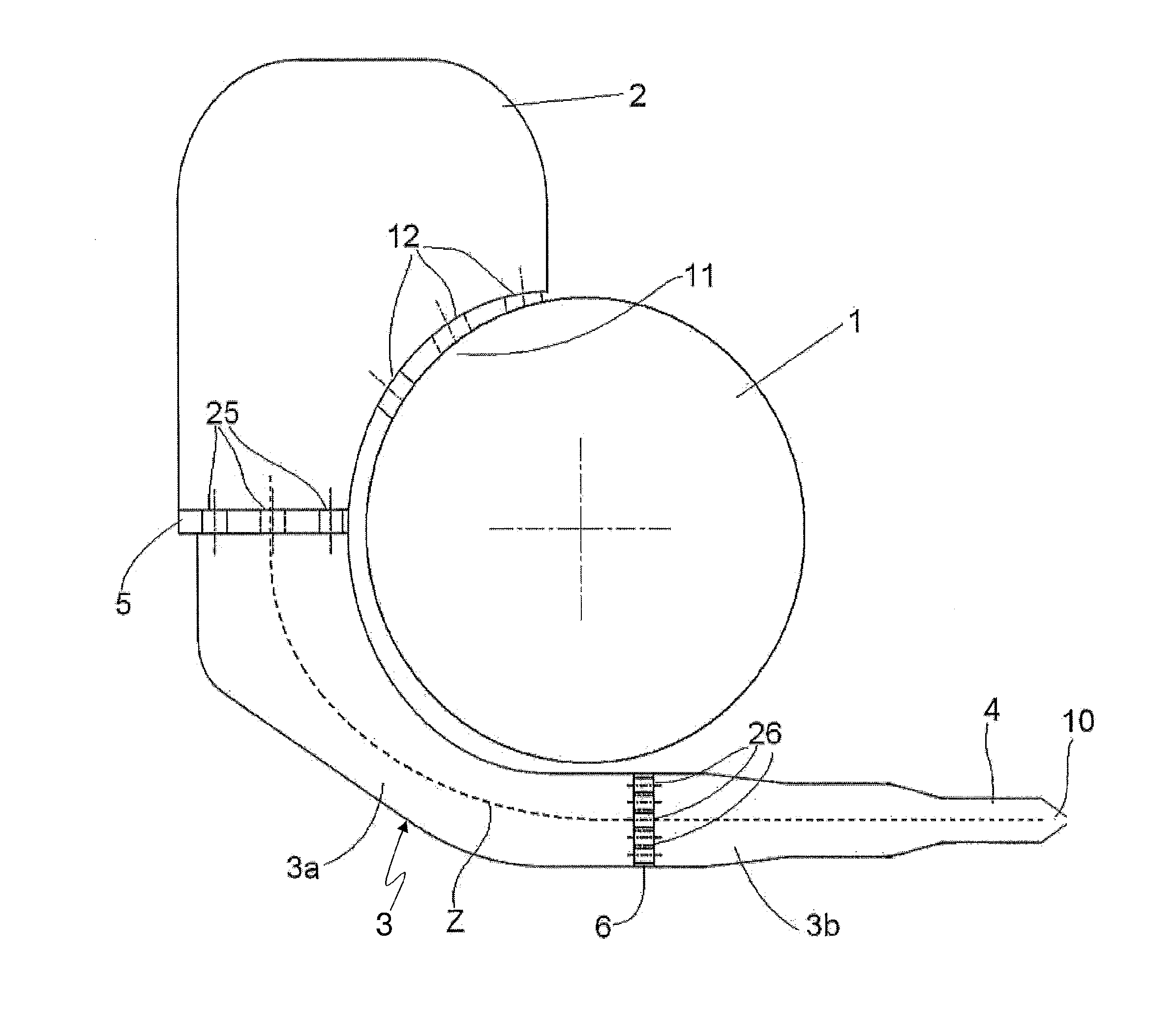
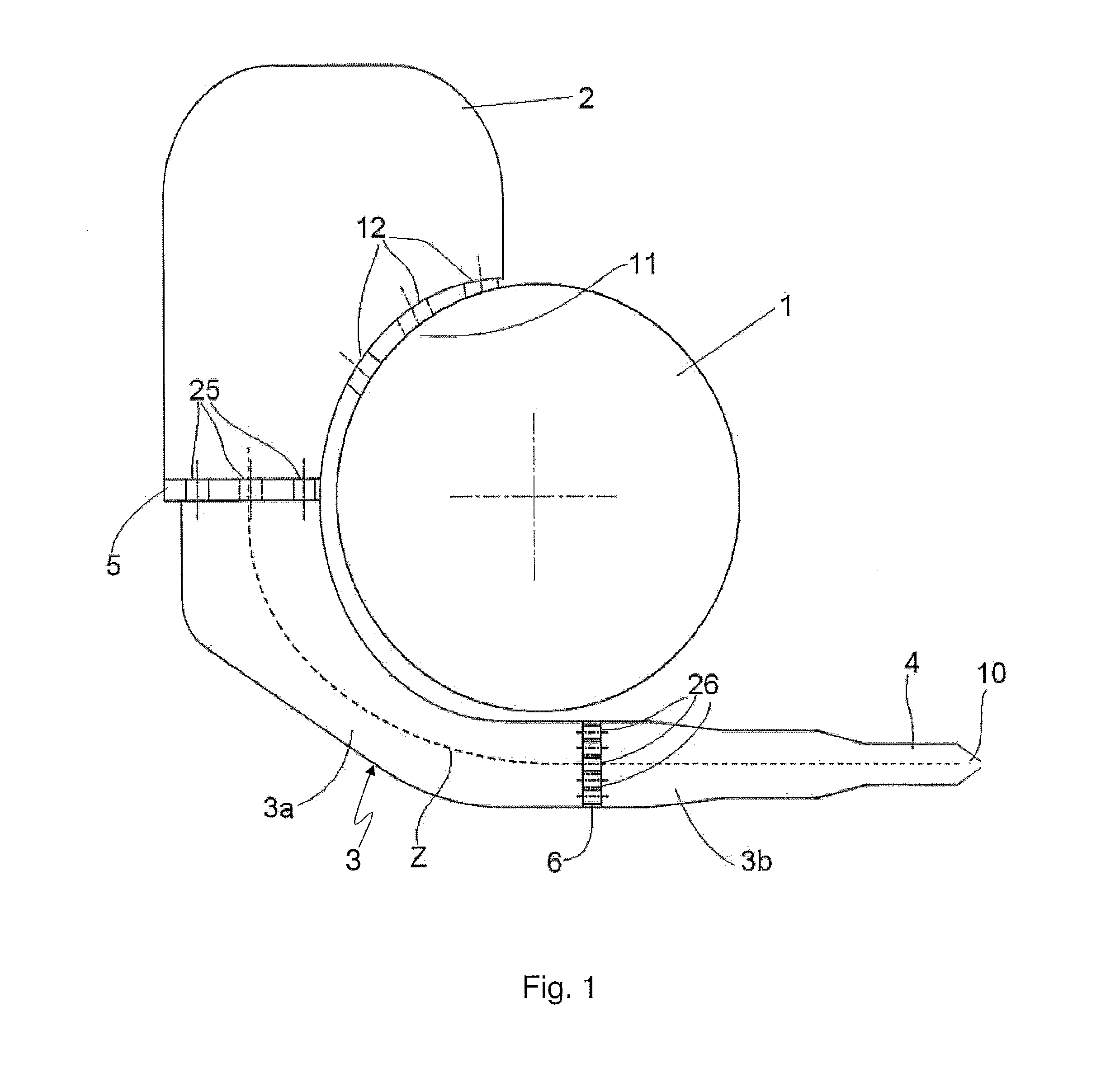
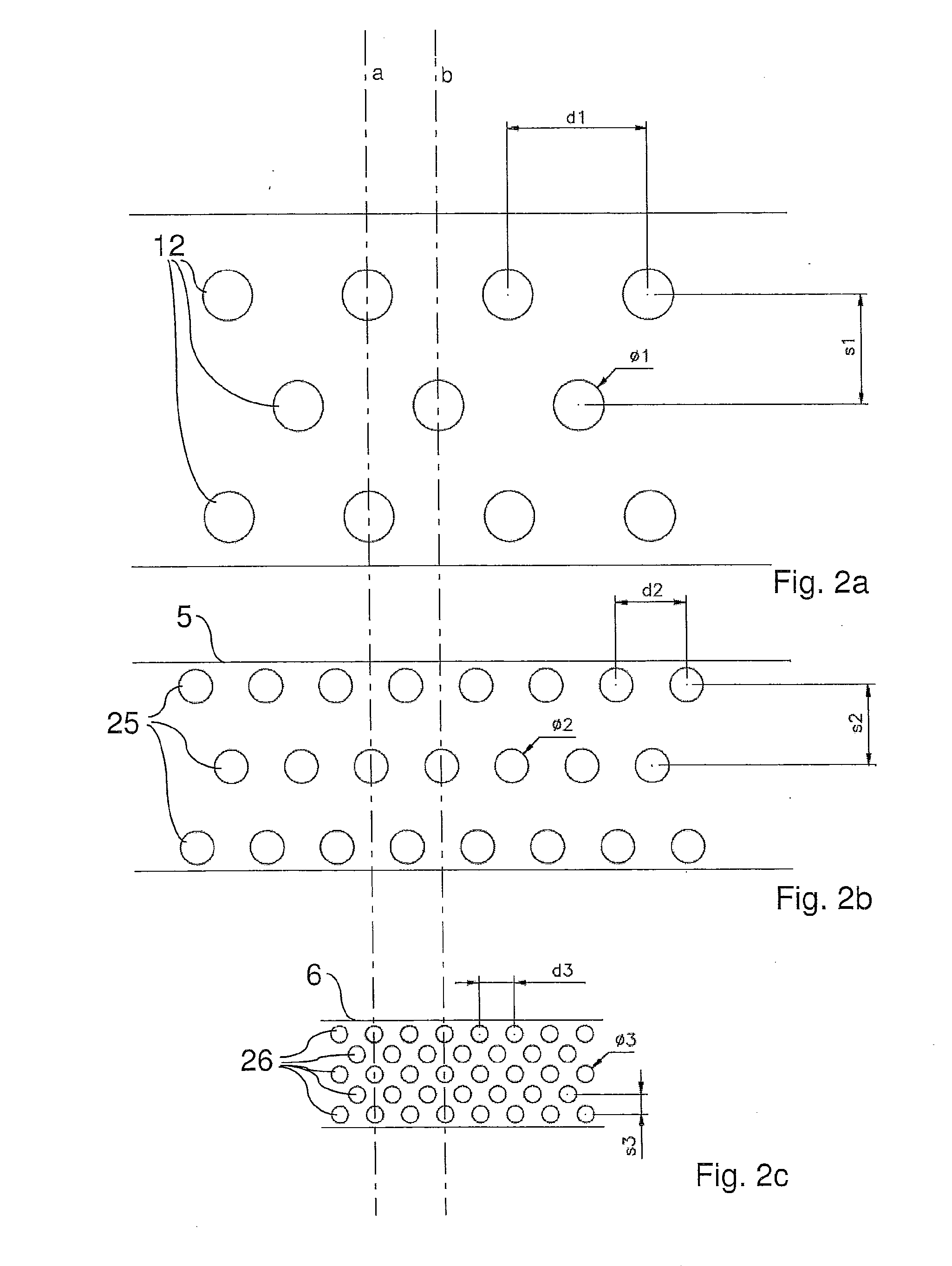
[0043]With reference to FIG. 1, a device to level a gas flow according to the present invention comprises a longitudinal delivery manifold 1 and a levelling pre-chamber 2 which directs the gas from delivery manifold 1 to levelling pipe 3, on which nozzle 10 is engaged. The peripheral wall of the delivery manifold, in a first longitudinal sector 11 of an angular extent of about 90°, over the whole length or longitudinal extension of said manifold, comprises first holes 12 for the gas to pass. In FIGS. 1 and 2a, for example, three rows of first holes 12 are provided. In other variants, the number of rows of first holes 12 may be different from three. Levelling pre-chamber 2 overlies the first longitudinal sector 11 in which holes 12 open, and is connected to a levelling pipe 3 divided into a first stretch or portion 3a which is wound on the delivery manifold 1 over about a second longitudinal sector, i.e. for about preferably 90°, and into a second stretch or portion 3b which substant...


PUM

PropertyMeasurementUnit
angleaaaaaaaaaa
widthaaaaaaaaaa
widthaaaaaaaaaa

Abstract

The device has a gas flow levelling pipe (3), which defines a continuous curved development surface (Z), at comprising a collector (4) to which a nozzle (10) is fixed, a delivery manifold (1), in order to introduce pressurized gas into the pre-chamber (2) through the holes (12), a first holed partition (5) and a second holed partition (6) within the levelling pipe (3), arranged perpendicular to the curved development surface (Z) of the pipe (3).

Description

FIELD OF THE INVENTION[0001]The present invention refers to a device for generating a gas flow in hot coating processes for metal strips. Such a device is also generally known as an air knife.STATE OF THE ART[0002]As known, the hot galvanizing process consists in coating zinc on steel strips, by immersing them into a bath of molten zinc (at 450° C.-470° C.) contained in a tank, on both faces and with variable coating thicknesses as a function of the final application. The process is of the continuous type; the steel strip is normalized and the two opposite surfaces are suitably prepared in order to obtain a perfect adhesion of the zinc to the basic steel and the formation of very thin, uniform zinc layer.[0003]The adjustment of the zinc coating thickness is obtained by means of an air knife system, which also allows the coating to be uniformly distributed on the two surfaces and over the whole length of the strip. The system of air knives essentially consists of two lips, defining a...

Claims


Application Information

Patent Timeline
Patent Type & Authority Applications(United States)
IPC IPC(8): B05C11/06
CPCC23C2/20B05C11/06C23C2/40
Inventor VECCHIET, FABIOCONA, ALESSANDROCAPORAL, GIANLUCA
Owner DANIELI & C OFF MEC SPA
Learn More