

Medium conveyance device and image formation apparatus
- Summary
- Abstract
- Description
- Claims
- Application Information
AI Technical Summary
Benefits of technology
Problems solved by technology
Method used
Image

Examples
first embodiment
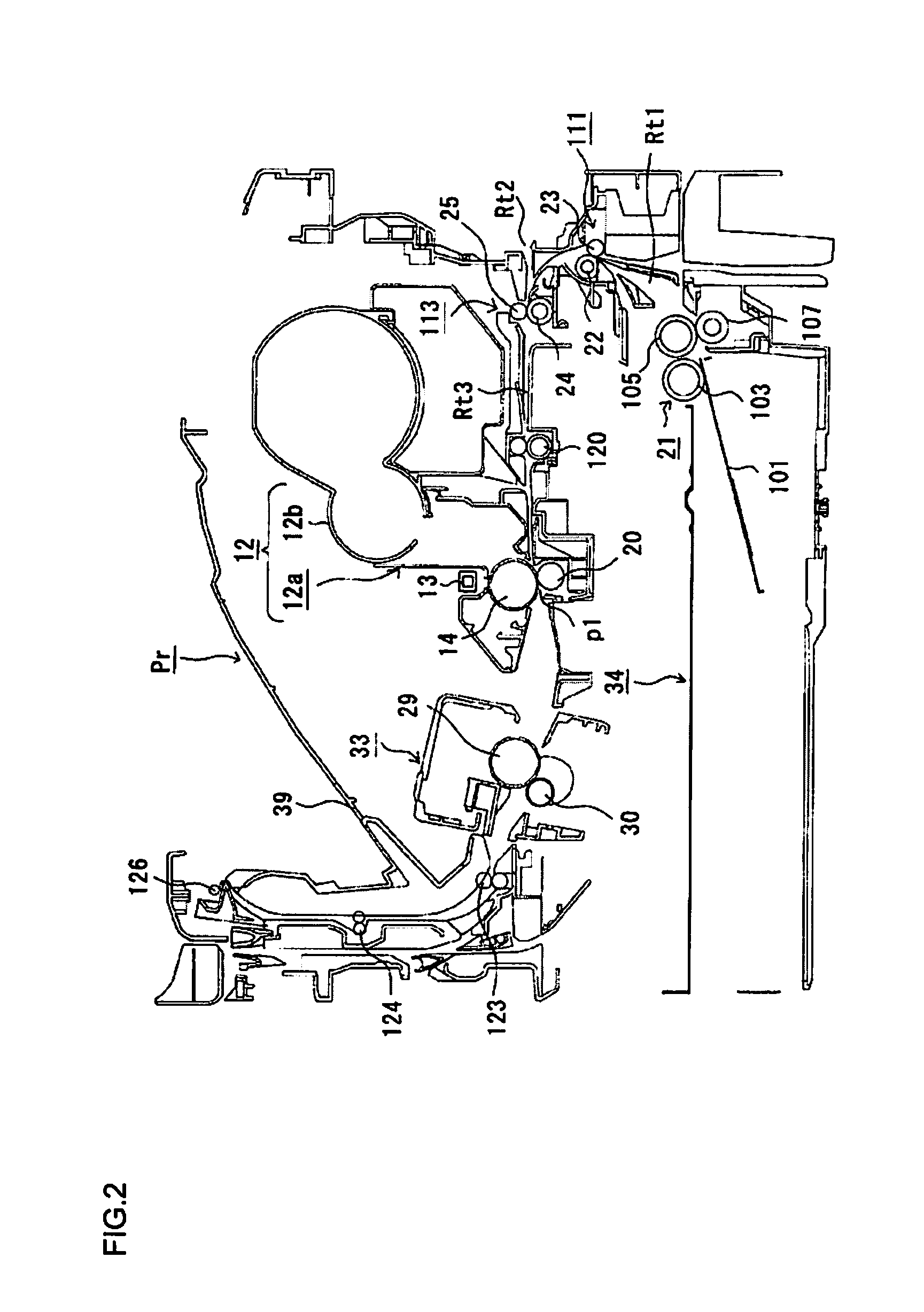
[0028]FIG. 2 is a schematic diagram of a printer of the invention.
[0029]In FIG. 2, Pr denotes the printer, and printer Pr includes components such as image formation unit 12 (an image carrier) in which photosensitive drum 14 is provided, LED head 13 (an exposure device) being provided for image formation unit 12 and facing photosensitive drum 14, transfer roller 20 (a transfer member) being provided for image formation unit 12 and facing photosensitive drum 14, and fixation device 33.
[0030]Image formation unit 12 includes image-formation-unit main body 12a, which is a main body of image formation unit 12, and toner cartridge 12b (a developer container) provided attachable to and detachable from image-formation-unit main body 12a and configured to contain toner (developer). Besides photosensitive drum 14, image formation unit 12a has provided therein a charge roller (a charge device), a development roller (a developer carrier), a development blade (a developer restriction member), a ...
second embodiment
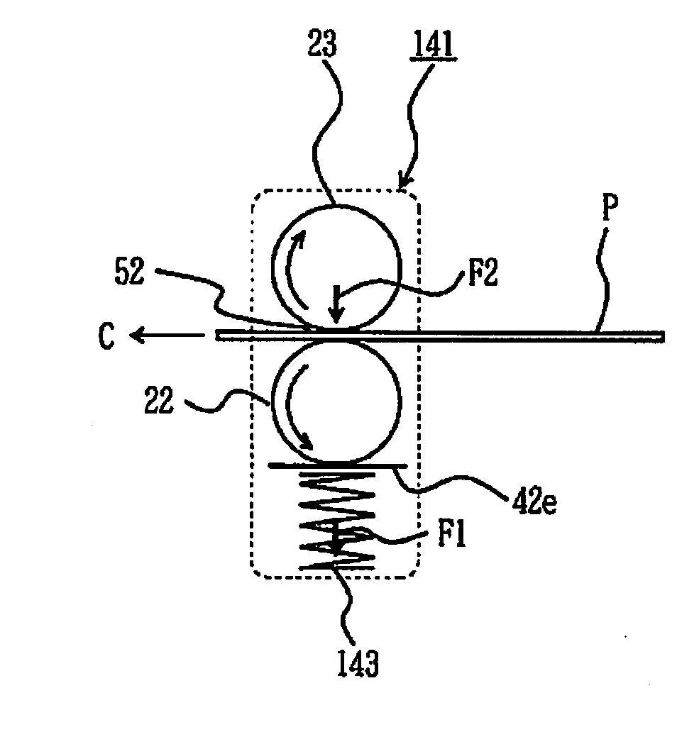
[0090]FIG. 11 is a diagram illustrating the operation of the second roller conveyance mechanism of the invention.
[0091]In the drawings, reference numeral 14 denotes a photosensitive drum (an image carrier), 20 denotes a transfer roller (a transfer member), 24 denotes the registration roller, 25 denotes the pressure roller, 143 denotes the spring, and 441 denotes the bearing holder.
[0092]Sheet P picked up by first medium pickup portion 21 from sheet cassette 34 (FIG. 2) (a first medium stacker or a medium container) and supplied to medium conveyance route Rt1 is temporarily stopped by first roller conveyance mechanism 111 to be corrected for its skew, and is then supplied to second roller conveyance mechanism 113.
[0093]Then, when the leading end of sheet P reaches registration roller 24 and pressure roller 25, pressure roller 25 moves away from registration roller 24 against a bias force of spring 143 (upward in FIG. 11). In this event, spring receiver 41f (FIG. 3) receives a reactio...
PUM
 Abstract
Description
Claims
Application Information