
Vehicle speed calculator, and vehicle including same

a calculator and vehicle technology, applied in the field of vehicle speed calculators, can solve problems such as errors, and achieve the effects of reducing the impact of errors on image recognition, reducing the impact of errors, and ensuring the large reference distan

Active Publication Date: 2014-07-31
HONDA MOTOR CO LTD
View PDF4 Cites 4 Cited by
  • Summary
  • Abstract
  • Description
  • Claims
  • Application Information

AI Technical Summary

Benefits of technology

The present invention relates to a device and method for accurately measuring the speed of a vehicle on a road surface using a reference distance mark. The device includes a reference distance mark irradiation unit that shines a beam of light in parallel with the optical axis of the image capturing unit. The two first laser pointers in the reference distance mark irradiation unit are placed close enough to each other to maintain the reference distance, even when there is a change in the vehicle's height. This ensures accurate measurement of the vehicle's speed, even during banking. The device is attached to the image capturing unit, which ensures high parallelism of the laser pointers' optical axes with the camera's optical axis, further improving the accuracy of vehicle speed calculation.

Problems solved by technology

However, the grid-shaped mark projected onto a road surface undergoes a change, for example, in width with change in vehicle height, making it likely that an error will occur at the time of conversion of the traveling speed of feature points obtained by optical flow into vehicle speed.

Method used


Image

  • Vehicle speed calculator, and vehicle including same
  • Vehicle speed calculator, and vehicle including same
  • Vehicle speed calculator, and vehicle including same

Examples


Embodiment Construction

[0046]An illustrative embodiment of the present invention will be described hereinafter in detail with reference to the accompanying drawings. Throughout this description, relative terms like “upper”, “lower”, “above”, “below”, “front”, “back”, and the like are used in reference to a vantage point of an operator of the vehicle, seated on the driver's seat and facing forward. It should be understood that these terms are used for purposes of illustration, and are not intended to limit the invention.

[0047]A detailed description will be given below of illustrative embodiments of the vehicle speed calculator according to the present invention with reference to the accompanying drawings.

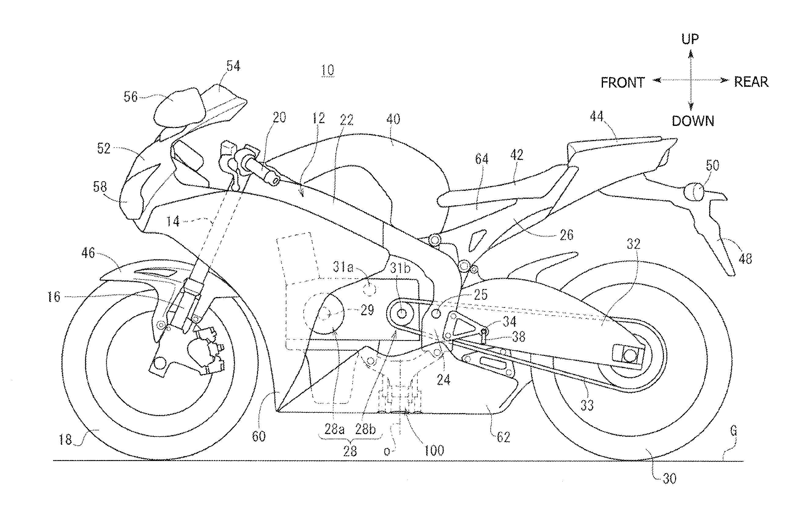
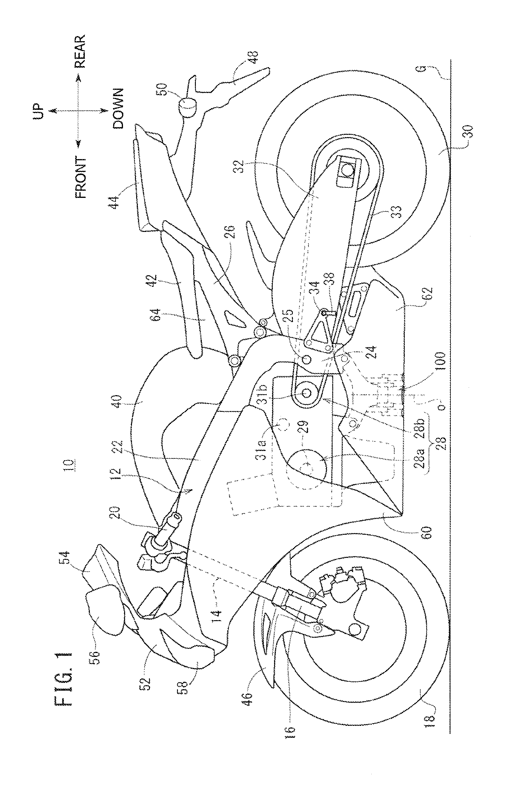
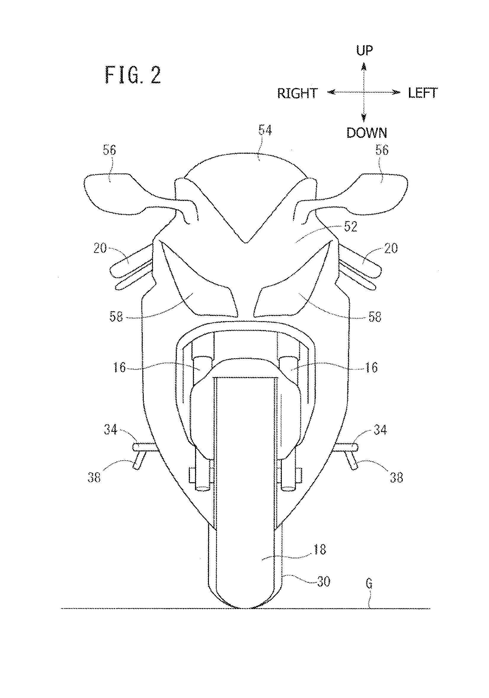
[0048]FIG. 1 is a side view of a motorcycle 10 to which the vehicle speed calculator is mounted. FIG. 2 is a front view of the motorcycle 10 shown in FIG. 1. It may be noted that, unless otherwise specified, the longitudinal, vertical and horizontal directions will be described in accordance with the direc...


PUM


Abstract

A vehicle speed calculator includes a vehicle speed calculation unit for calculating a vehicle speed from a traveled distance per unit time of a feature point in a captured image shot by a camera for capturing a road surface, a reference distance mark irradiation unit and an image reference distance detection unit. The reference distance mark irradiation unit irradiates a reference distance mark to the road surface in parallel with an optical axis of the camera. The reference distance mark is formed in such a manner as to have a reference distance in a longitudinal direction of a motorcycle. The image reference distance detection unit detects an image reference distance, the longitudinal length of the reference distance mark in the shot image. The vehicle speed calculation unit calculates the vehicle speed from the traveled distance using the image reference distance and the reference distance.

Description

CROSS-REFERENCE TO RELATED APPLICATIONS[0001]The present invention claims priority under 35 USC 119 based on Japanese Patent Application No. 2013-017647, filed on Jan. 31, 2013. The entire subject matter of this priority document, including specification claims and drawings thereof, is incorporated by reference herein.BACKGROUND OF THE INVENTION[0002]1. Field of the Invention[0003]The present invention relates to a vehicle speed calculator for calculating vehicle speed by shooting a road surface, and to a vehicle including the same. More particularly, the present invention relates to a vehicle speed calculator which provides improved calculation accuracy of vehicle speed even when there is a change in vehicle height, and to a motorcycle including the same.[0004]2. Description of the Background Art[0005]There is known technique for shooting a road surface with a camera attached to a vehicle so as to measure a traveling speed and angle of the road surface relative to the camera and us...

Claims


Application Information

Patent Timeline
Patent Type & Authority Applications(United States)
IPC IPC(8): G06T7/20
CPCG06T7/20G01P3/806B60W40/105B60Y2200/12B62J45/4151B62J45/20B60W2420/408B60W2420/403
Inventor ONO, TETSUYA
Owner HONDA MOTOR CO LTD
Learn More