Magnetic construction system and method

a construction system and magnetic technology, applied in the field of magnetic construction systems, can solve the problems of 50% of users having to flip any given piece prior to attachment, inability to remove an internal part without, and difficulty in assembly, so as to promote the ability to efficiently stack or nest structural bodies. the effect of increasing the magnetic coupling for

Active Publication Date: 2014-07-31
FERGUSON JOSHUA WILLARD
View PDF67 Cites 43 Cited by
  • Summary
  • Abstract
  • Description
  • Claims
  • Application Information

AI Technical Summary

Benefits of technology

[0016]Embodiments of the present invention include structural bodies and permanent dipole magnets. Each structural body is constructed of two or more permanently attached structural parts which together form one or more pockets, and each pocket has two equal and opposed outward-facing openings of restricted aperture. These pockets serve to capture a corresponding number of permanent magnets which are free to rotate to magnetically align with magnets in adjacently positioned structural bodies. The outward facing surface of each magnet is partially exposed through the openings the exposed portions able to contact or to come within close proximity with a like exposed surface of other magnets, thereby increasing magnetic coupling force. Two or more magnetically coupled structural bodies are able to rotate with respect to one another about the axis of magnetic coupling in either an indexed and clicking manner via detents, or alternatively in an arrangement allowing free and smooth rotation between respective parts.
[0017]In one implementation, an underlying geometry of each structural body is based on an extended pattern of efficiently nested, equal-sized equilateral triangles, wherein: a) each triangle apex is coincident with the apex of five other like triangles; b) every side of every triangle is coincident with one side of an adjacent triangle; c) any adjacent apex of any triangle, separated by a single triangle side length, represents a possible magnet position within the structural body; d) the perimeter geometry of the structural body surrounding any such magnet position (hereafter ‘magnetic node’ or ‘node’) is comprised of one or more radial arcs with said possible magnet locations as center points, with all such radii substantially equal in dimension and substantially equating to half the length of a side of the equilateral triangle. Magnetically coupled nodes therefore share the same underlying equilateral pattern, promoting the ability to efficiently stack or nest structural bodies in a manner consistent with the underlying pattern. Stacking includes the use of multiple overlapping or overlaying planes, each plane conforming to the underlying geometry of the extended pattern with magnet locations aligned across planes. In addition, the geometry of specific parts allows out-of-plane constructions in which two or more planes of the extended pattern may intersect.

Problems solved by technology

Despite the building flexibilities provided by press-fit attachment methods, there are also some common drawbacks, such as difficulty of assembly, and later disassembly, especially by younger children, and generally the inability to remove an internal part without first removing parts attached thereupon.
However, this fixed dipole arrangement means a user has a 50% chance of needing to flip any given piece prior to attachment.
For multilayer systems, it may difficult, if possible, to flip a connecting part, especially parts having multiple magnets which all must have a proper predetermined orientation.
However, the need for a separate ferromagnetic part impacts system architecture, ease of construction, safety, and overall cost.
However, this approach has corresponding shortcomings, and brings up the additional safety concerns associated with the risk of children ingesting two or more loose magnets and having them internally magnetically couple.
This bi-stable coupling behavior may be considered desirable in one respect, by helping part edges to align along their linear edge geometry, but it also means that this magnet architecture it not suitable for applications in which smooth and continuous rotation is desirable, such as with magnetically attached wheels, gears, or chain segments.
Furthermore, the combined thickness of two intermediate part walls between coupled magnets reduces magnetic coupling force significantly, therefore requiring larger or stronger magnets for any desired connection strength and commensurately increasing overall system cost.
Two such magnetically coupled parts could rotate with respect to one another but may experience considerable rotational friction between contact surfaces due to the local clamping load applied by the respective magnets.
Furthermore, such a magnetic coupling may not provide sufficient rotational stability to allow for stable structures, especially when the magnetic coupling axis is oriented horizontally and the weight of attached parts may cause unwanted rotation or bending / sagging of parts about said axis.
Parts may rotate with respect to one another about this magnetic coupling, via the capability of either magnet to rotate within its retaining pocket, but the interposing surfaces may experience significant friction due to the clamping force exerted by the magnets, thereby resisting rotation, while the wall thickness of the retaining walls detracts from the coupling force of the magnets.
However, this system has no provision for providing rotational stability between coupled structural bodies when so desired, and requires multiple additional parts for the subassembly required in each magnet location.
In this arrangement, relative rotation of magnetically coupled parts is always achieved in an indexed fashion, and is not capable of free rotation when so desired.
As before, the part count and complexity of each pivotable magnetic subassembly translates to increased overall cost.
In summary, various magnetic construction systems may employ different mechanisms and methods of aligning magnetic polarity between parts, but not in a manner which comprehensively enables self-alignment of magnets via geometric rotation while also enabling any magnetic coupling to serve either as a freely rotatable, low-friction axis of rotation when desired (such as for wheels, gears, or chains links), or as a rotationally stable connection point with indexed rotation detents suitable for structural stability.

Method used


Image

  • Magnetic construction system and method
  • Magnetic construction system and method
  • Magnetic construction system and method

Examples


Embodiment Construction

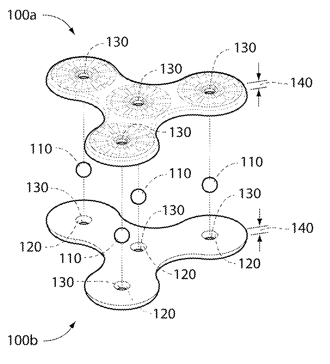
[0068]Embodiments of the present invention provide an architecture and method for creating a magnetic construction system including two or more structural bodies each capturing one or more partially exposed, rotatable and self-aligning magnets. The unique structural aspects of the present invention are illustrated herein via various illustrative embodiments, as will now be described in detail. The following description is presented to enable one of ordinary skill in the art to make and to use the invention, and is provided in the context of a patent application and its requirements.

[0069]Various modifications to the preferred embodiment and to the generic principles and features described herein will be readily apparent to those skilled in the art. Thus, the present invention is not intended to be limited to the embodiments shown but is to be accorded the widest scope consistent with the principles and features described herein.

[0070]FIG. 1 illustrates an exploded view of two struct...


PUM


Abstract

A magnetic construction system comprised of plural multi-shaped structural bodies each containing one or more captured magnets, wherein each magnet is free to rotate within its respective retaining pocket to align in magnetic polarity with rotatable magnets in adjacent structural bodies. Surface geometry around each magnet may include a radial detent feature which provides lateral and rotational stability between magnetically coupled structural bodies, or a radial recess which allows free rotation of respective structural bodies about the polar axis of magnetic coupling.

Description

CROSS REFERENCE TO RELATED APPLICATIONS[0001]This application claims the benefit of U.S. Provisional Application 61 / 759,189 filed on Jan. 31, 2013, the contents of which are hereby expressly incorporated by reference for all purposes.FIELD OF THE INVENTION[0002]This invention relates generally to magnetic construction systems, and more specifically, but not exclusively, to magnetic construction systems using permanent dipole magnets rotatably retained within corresponding pockets in multiple structural bodies which may attract, one to another, via the ability of the respective magnets to rotate as needed for proper orientation and alignment of opposite magnetic poles.BACKGROUND OF THE INVENTION[0003]The subject matter discussed in the background section should not be assumed to be prior art merely as a result of its mention in the background section. Similarly, a problem mentioned in the background section or associated with the subject matter of the background section should not be...

Claims


Application Information

Patent Timeline
Patent Type & Authority Applications(United States)
IPC IPC(8): A63H33/04
CPCA63H33/046A63H17/002
Inventor FERGUSON, JOSHUA WILLARD
Owner FERGUSON JOSHUA WILLARD
Why Eureka
Try Eureka