
Snow rake with telescoping pole

a telescopic and rake technology, applied in snow cleaning, handbags, manufacturing tools, etc., can solve the problems of difficult decoupling of pole segments, fixed length of assembly at certain increments of length, and difficult to achieve, so as to prevent axial separation of pole segments

Active Publication Date: 2014-08-07
SUNCAST TECH
View PDF8 Cites 51 Cited by
  • Summary
  • Abstract
  • Description
  • Claims
  • Application Information

AI Technical Summary

Benefits of technology

The snow rake with telescoping pole has a blade for pulling snow from surfaces like roofs. It has a pole with segments that move axially and are keyed to resist rotation. A lock device secures the pole segments at different positions. The technical effect is a snow rake that is easy to use and secure for different types of snow removal.

Problems solved by technology

While effective, such pole segments are typically aluminum for weight and price considerations, and will have thin walls that are easily permanently deformed rendering them non-usable.
While effective in locking, this can be difficult to accomplish while wearing gloves in cold weather.
It is similarly difficult to decouple the pole segments.
Another problem with this type of multi segment type of pole is that the length of the assembly is fixed at certain increments of length.
However, such a construction positively prevents relative longitudinal and rotational movement between pole segments.
Typically these are not very effective devices because of the difficulty in obtaining enough friction to prevent relative movement between pole segments, either longitudinally or rotationally.
Experience with a split collet type friction device indicates these are not typically effective and difficult to use, particularly when wearing gloves and when the axial force to be applied to pull a load is large.

Method used


Image

  • Snow rake with telescoping pole
  • Snow rake with telescoping pole
  • Snow rake with telescoping pole

Examples


Embodiment Construction

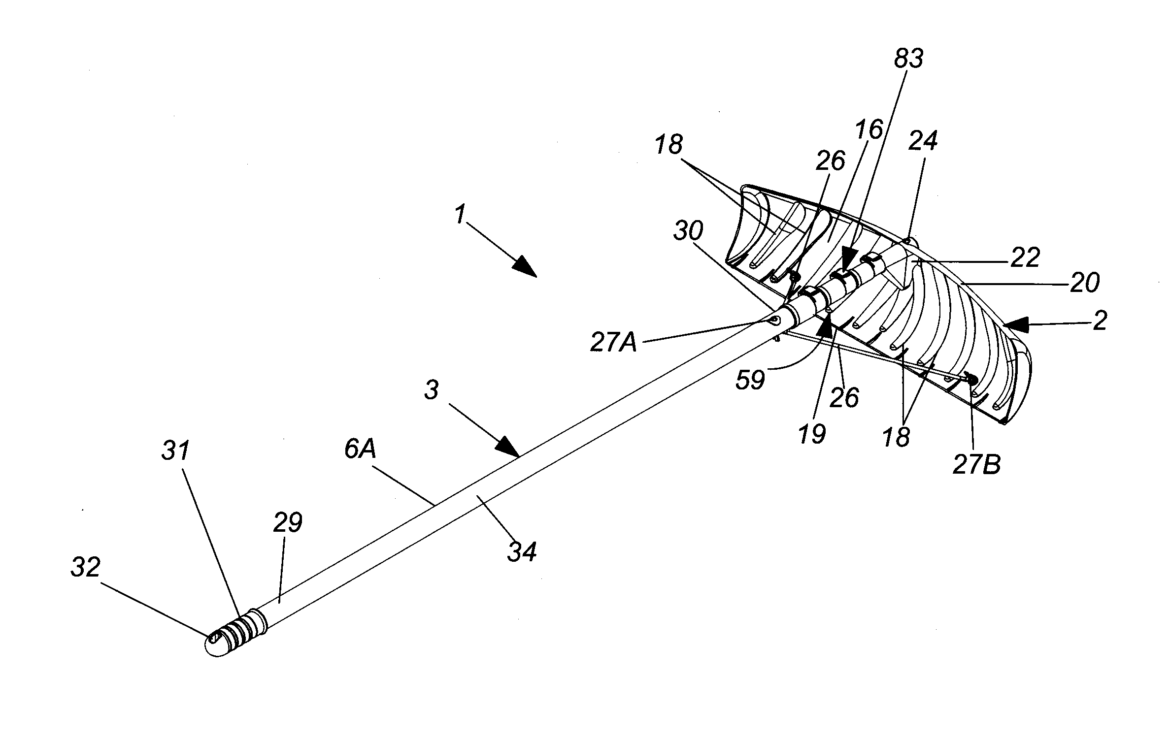
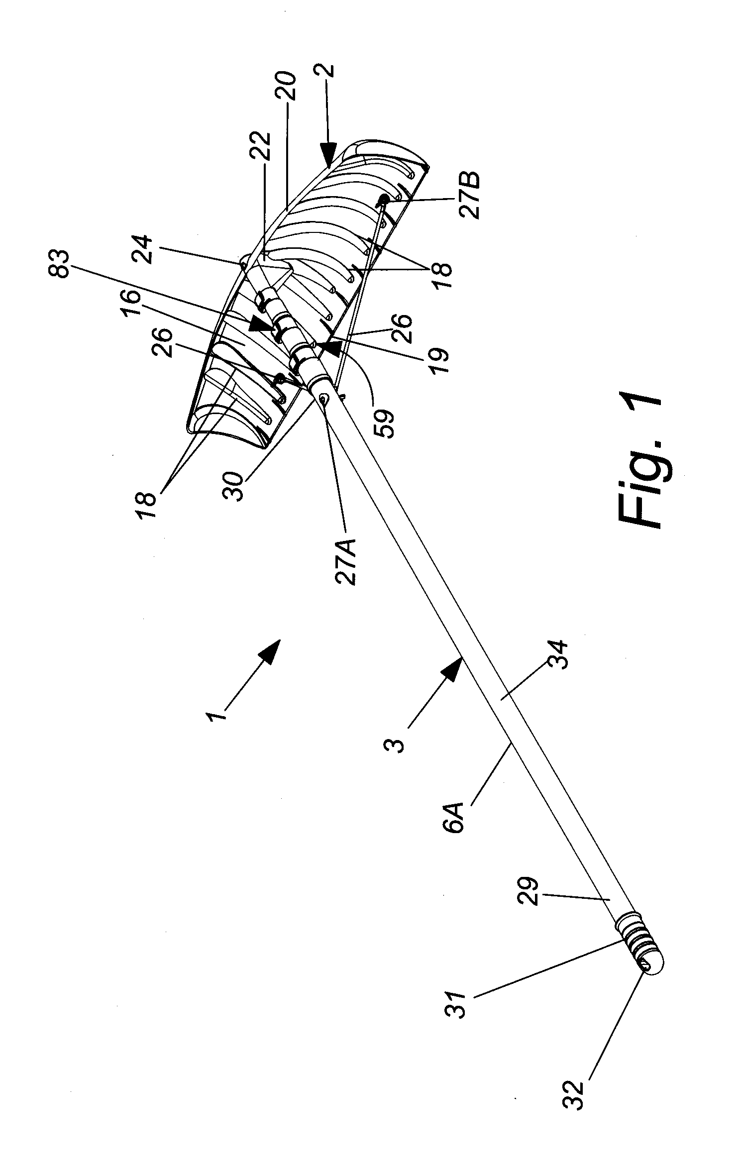
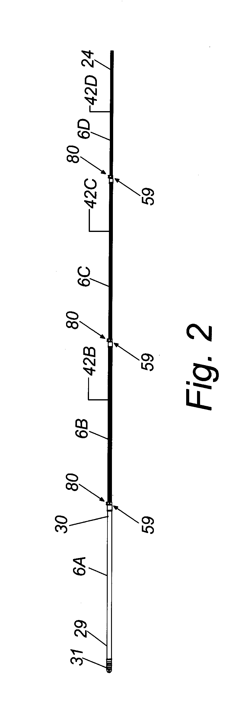
[0014]Referring to FIG. 1, a snow rake, designated generally as 1, is illustrated. The rake 1 includes a blade 2 and a telescoping pole 3. It is to be understood that the pole 3 can be used with other implements such as a saw blade, squeegee and the like. The pole 3 includes a plurality of pole segments which are illustrated as four in quantity and are designated 6A, 6B, 6C and 6D with the pole segments being in telescoping relationship with the segment 6B being slidably received in segment 6A and adjacent thereto, the segment 6C being slidably received in the segment 6B and adjacent thereto and the segment 6D being slidably received in segment 6C and adjacent thereto. See FIG. 2. Any suitable number of segments 6 can be provided in a quantity of two or more as desired.

[0015]The blade 2 can be of any suitable shape and, as shown, has a concave surface 16 from which the pole 3 extends. The surface 16 is positioned for normally engaging material such as snow when the blade 2 is moved ...


PUM


Abstract

A telescoping pole and blade to form a snow rake. The pole has a plurality of segments selectively axially movable relative to one another. The pole segments are keyed to one another to prevent relative rotation between adjacent pole segments. A lock device is associated with adjacent pairs of pole segments to selectively fix the relative axial positions of the pairs of pole segments.

Description

FIELD OF INVENTION[0001]A snow rake with telescoping pole is provided. The rake includes a blade for contacting snow and moving it with a pulling force by the user. The pole has a plurality of segments selectively axially movable relative to one another forming a telescoping arrangement.BACKGROUND OF THE INVENTION[0002]Snow rakes for use in removing snow from a roof or the like are known in the art. They typically comprise a blade connected to a pole. There may also be braces connected to and extending between the blade and the pole to help the blade resist bending under load. The poles are typically of a multi-segment type that requires assembly by connecting the segments together to obtain a desired pole length for use of the rake. While effective, such pole segments are typically aluminum for weight and price considerations, and will have thin walls that are easily permanently deformed rendering them non-usable. Even a minor distance drop onto a hard surface can deform a pole seg...

Claims


Application Information

Patent Timeline
IPC IPC(8): E04D13/00B25G1/04
CPCB25G1/04E04D13/00E04D13/106
Inventor FISCHER, JR., GARY M.VOGLER, MICHAEL R.
Owner SUNCAST TECH
Learn More