Tower assembly and method for assembling tower structure

a technology for tower structures and components, applied in the field of tower structures, can solve the problems of difficult inspection, difficult initial installation and joining of post-tensioning devices, and difficult fabrication of structural components, etc., and achieve the effects of improving structural integrity, facilitating inspection, and facilitating fabrication of structural components

Active Publication Date: 2014-08-07
TINDALL CORP
View PDF29 Cites 17 Cited by
  • Summary
  • Abstract
  • Description
  • Claims
  • Application Information

AI Technical Summary

Benefits of technology

[0020]The tendons may be joined by anchors. A tensile force may be applied to the tendons, and the anchors may secure the tendons and maintain such tensile force. The tensile force may cause the structural components to be subjected to a circumferential compressive force, such that the structural components are forced inward towards the inner bore. Such circumferential compressive force serves to stabilize the structure.
[0021]Because the tendons and anchors are generally external to the structural components, the post-tensioning devices of the present disclosure provide structural support to tower structures while providing ease of installation, ease of inspection, and ease of fabrication of the structural components.
[0022]Further, the use of post-tensioning devices in combination with a thixotropic filler material is particularly advantageous. For example, the thixotropic filler material may be provided between neighboring structural components, and may be allowed to cure, before the post-tensioning devices are subjected to the tensile force as discussed above. When the tensile force is provided, and the structural components are thus subjected to the circumferential compressive force, the compressive forces are transmitted across and thus distributed by thixotropic filler material. Thus, the combined use of post-tensioning devices and thixotropic filler materials provides tower assemblies with significantly improved structural integrity and which are relatively efficient and inexpensive to assemble.

Problems solved by technology

Thus, such known post-tensioning devices are difficult to initially install and join together for post-tensioning, and are also difficult to inspect.
Further, because the conduits in the structural components typically are defined through a substantial portion of the width or length of the structural components, the structural components are difficult to fabricate.
Further, typically filler materials are difficult, time-consuming and expensive to utilize during construction of a tower structure.
Further, typical grout materials for tower structure applications, if not installed correctly, may not provide the desired structural support due to the existence of air bubbles and other defects.
Additionally, the use of known post-tensioning devices and filler materials together is exceedingly difficult, due to the inability to access the post-tensioning devices as discussed above and combined with the use of a filler material that may further impede access to the post-tensioning devices.
Thus, the stabilizing and structural advantages potentially provided by the post-tensioning devices and filler materials may in many cases not be fully realized.

Method used


Image

  • Tower assembly and method for assembling tower structure
  • Tower assembly and method for assembling tower structure
  • Tower assembly and method for assembling tower structure

Examples


Embodiment Construction

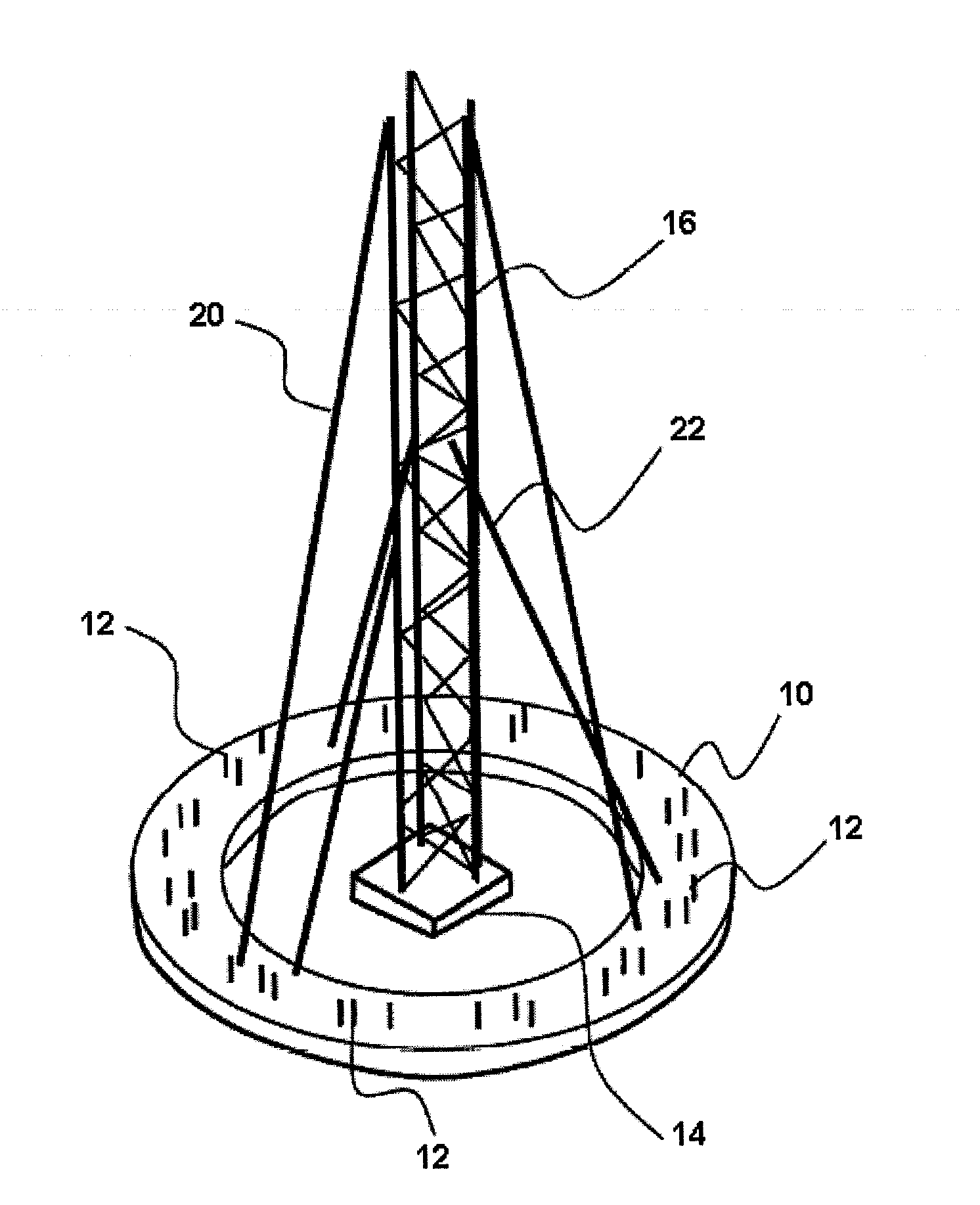
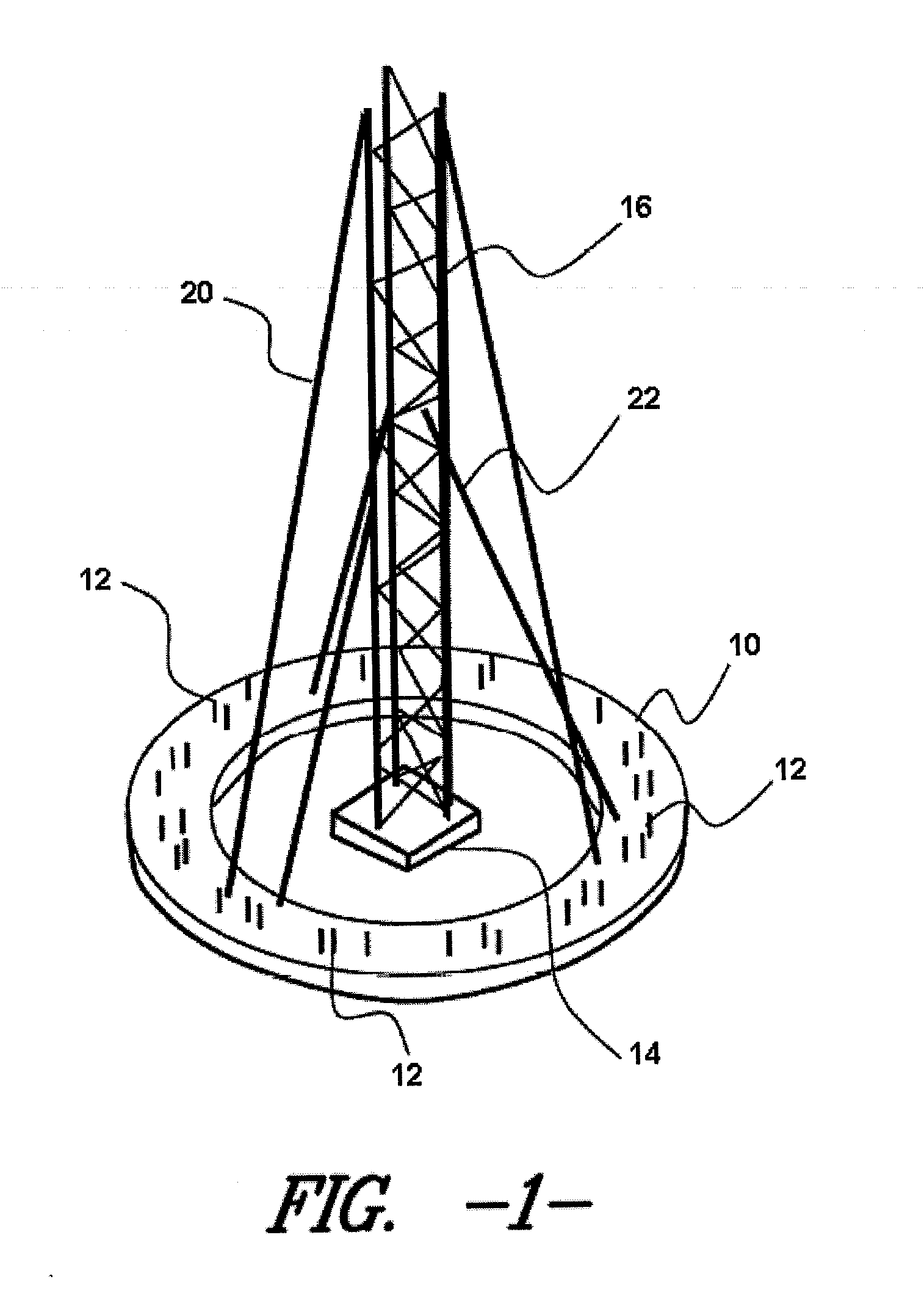
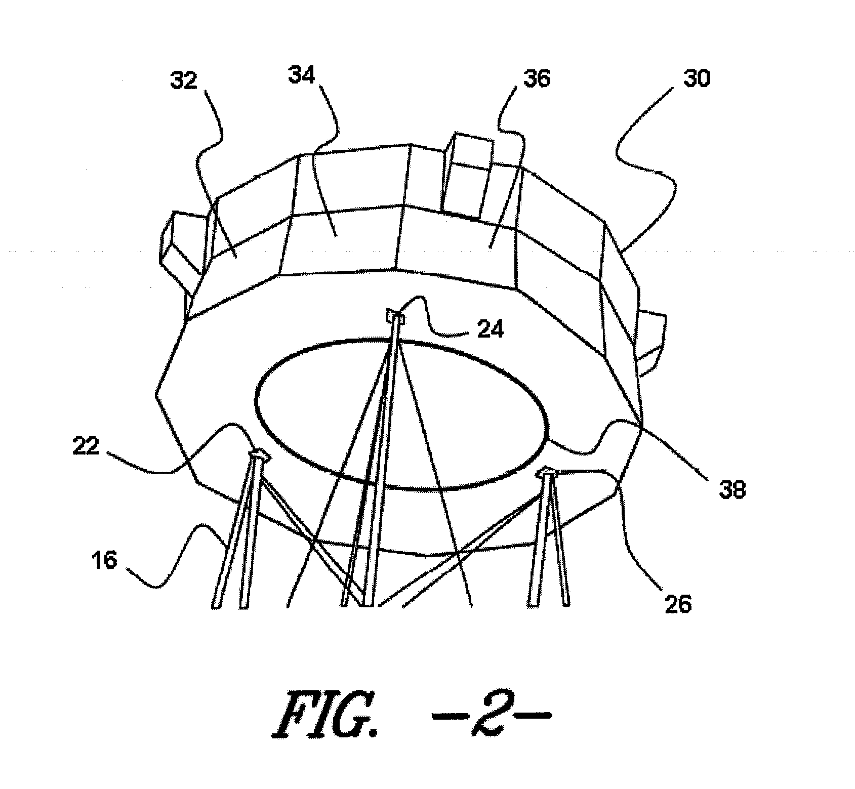
[0036]Reference is presently made in detail to exemplary embodiments of the present subject matter, one or more examples of which are illustrated in or represented by the drawings. Each example is provided by way of explanation of the present subject matter, not limitation of the present subject matter. In fact, it will be apparent to those skilled in the art that various modifications and variations can be made in the present subject matter without departing from the scope or spirit of the present subject matter. For instance, features illustrated or described as part of one embodiment can be used with another embodiment to yield a still further embodiment. Thus, it is intended that the present subject matter covers such modifications and variations as come within the scope of the disclosure and equivalents thereof.

[0037]With reference to present FIGS. 1-4, an exemplary embodiment of a present apparatus devised as an exemplary base support for wind-driven power generators will be d...


PUM


Abstract

A structure including at least two structural components arranged to form a channel therebetween, a post tensioning element configured to compress the at least two elements with respect to each other, and a thixotropic filler material located within the channel.

Description

CROSS-REFERENCE TO RELATED APPLICATIONS[0001]This application claims priority under 35 U.S.C. §119 (e) to U.S. Application No. 61 / 760,924, filed Feb. 5, 2013, the entire content of which is incorporated into the present application by reference.FIELD OF THE INVENTION[0002]The present subject matter relates generally to tower structures, and more specifically to methods and apparatus for assembling tower structures.BACKGROUND OF THE INVENTION[0003]Construction of towers for support of various items has been practiced for many years. Various towers of various materials, including wooden, steel, and, more recently, concrete, have been provided to support, for example, electrical transmission lines. In like manner, wind driven apparatus including windmills and wind-driven power generators in various forms and designed for many purposes (including for example pumping of water from wells as well as, more recently, generation of electrical power) have also been developed.[0004]Various appa...

Claims


Application Information

Patent Timeline
Patent Type & Authority Applications(United States)
IPC IPC(8): E04H12/00
CPCE04H12/00E04H12/10E04H12/20F05B2240/912H01Q1/1242Y02E10/728F03D13/20E04H12/16Y02E10/72Y02P80/10E04B1/16E04B1/4185F03D80/82F03D80/60
Inventor ZAVITZ, BRYANT A.KNOX, ROGER C.
Owner TINDALL CORP
Why Eureka
Try Eureka