Check Valves, Systems and Methods of Operation of Same

a technology of check valves and valve bodies, applied in the field of check valves, can solve the problems of fluid accumulation against the sealing element, valve vibration or “chattering effect”, valve operation means/release devices, etc., and achieve the effect of preventing the possibility of pressure drop

Inactive Publication Date: 2014-08-07
PENTAIR VALVES & CONTROLS ITAL SRL
View PDF10 Cites 3 Cited by
  • Summary
  • Abstract
  • Description
  • Claims
  • Application Information

AI Technical Summary

Benefits of technology

[0008]The present invention is based on the idea of forcing the sealing element of a check valve in a non-sealing position corresponding to an opening degree of the valve which is equal to or higher than a first predefined opening degree when the increase of the opening degree of the valve with respect to the sealing position of the sealing element is equal to or greater than a predefined threshold. In this way, as soon as the valve is open with respect to the sealing position by a predefined opening degree, the sealing element is forced to remain open so as to prevent the possible decrease of the pressure due to the opening of the valve causing the closing of the sealing element and thus, giving rise to the so-called “chattering” effect or vibration of the sealing element.

Problems solved by technology

If, on the other hand, the rate of the fluid flowing in the opening direction of the valve is not enough to displace the sealing element, then the valve does not open.
One of the major problems concerning check valves is the vibration of the sealing element or “chattering effect” of the valve.
Specifically, when the pressure of the fluid is too low to displace the sealing element from the sealing position, the fluid accumulates against the sealing element and the pressure starts to increase.
This effect is particularly undesired because the continuous vibration of the sealing element may damage the valve.
Specifically, the seal of the valve will deteriorate.
Furthermore, both the sealing element and the seat of the valve, with which the sealing element forms the seal, may be damaged by the vibration of the sealing element.
In particular, when the rate of flow of the fluid flowing through the valve is adequate enough to cause a rotation of the shaft around its longitudinal axis only by an angle comprised between 1° and 5° with respect to the position of the shaft corresponding to the closed sealing element, it is very likely that the chattering effect will arise.

Method used


Image

  • Check Valves, Systems and Methods of Operation of Same
  • Check Valves, Systems and Methods of Operation of Same
  • Check Valves, Systems and Methods of Operation of Same

Examples


Embodiment Construction

[0037]In the following, the present invention is described with reference to particular embodiments as shown in the enclosed drawings. Nevertheless, the present invention is not limited to the particular embodiments described in the following detailed description and shown in the Figures, but, instead, the embodiments described simply exemplify several aspects of the present invention, the scope of which is defined by the appended claims.

[0038]Further modifications and variations of the present invention will be clear for the person skilled in the art. Therefore, the present description has to be considered as including all the modifications and / or variations of the present invention, the scope of which is defined by the appended claims.

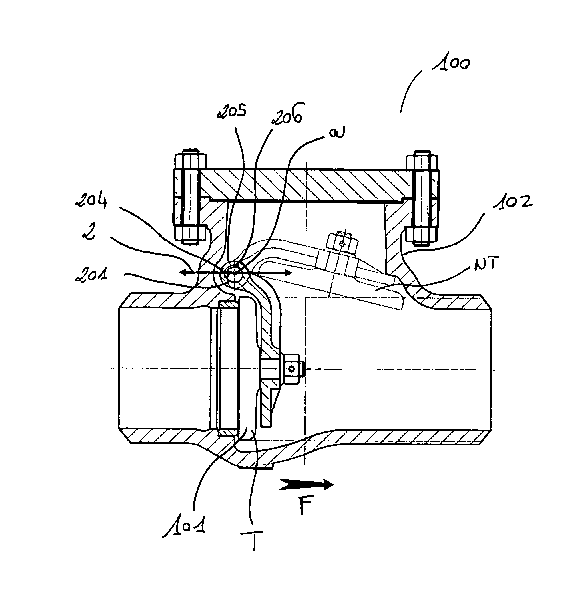
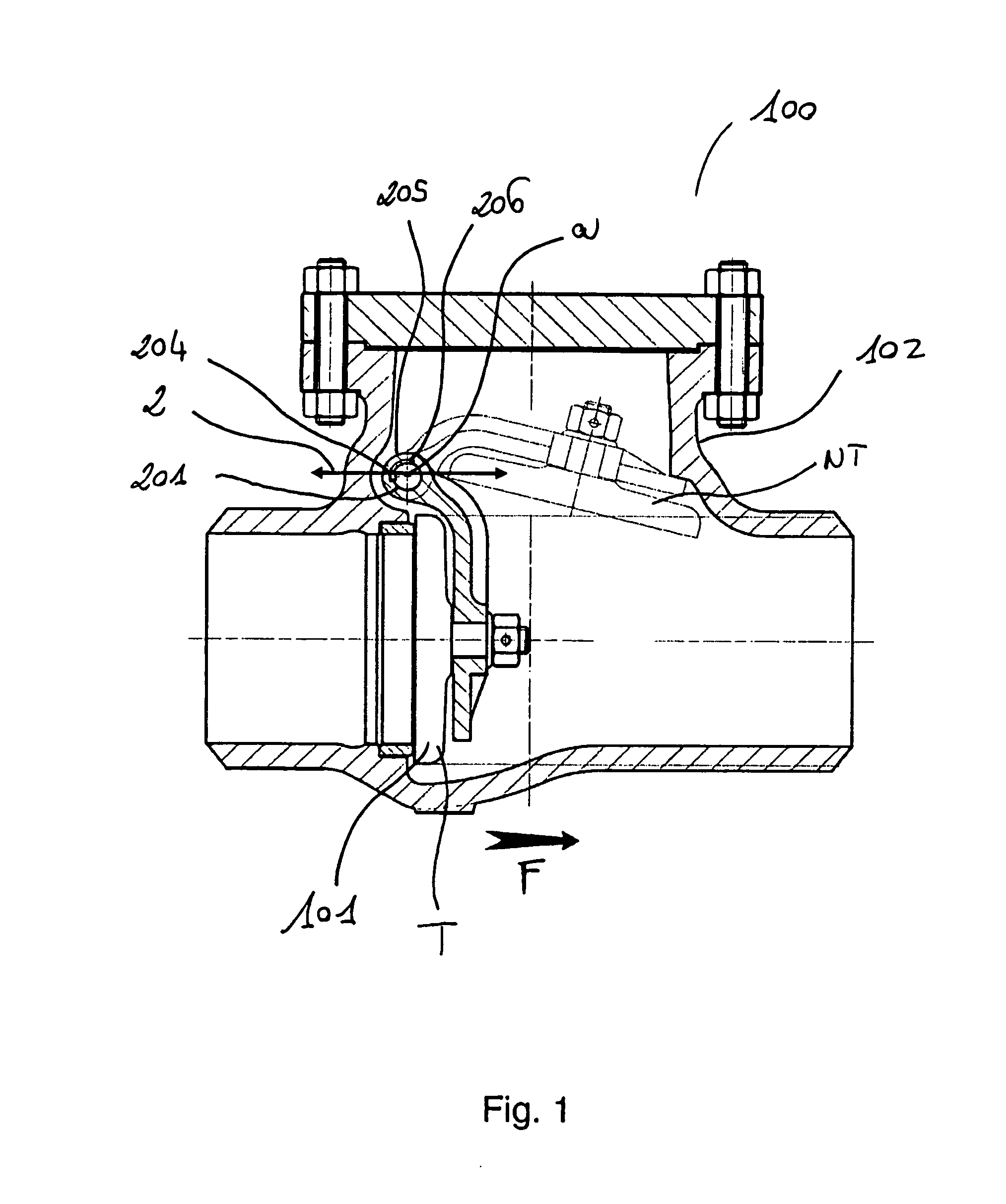
[0039]FIG. 1 schematically displays a section of a check valve 100 according to an embodiment of the present invention. The opening direction is shown by arrow F. In particular, arrow F shows the direction of the flow flowing through the valve 100 du...


PUM


Abstract

A system and a method for actuating a sealing element (101) of a check valve (100) are shown wherein the sealing element (101) is forced to a non-sealing position corresponding to an opening degree of the valve (100) equal to or higher than a first predefined opening degree when the increase of the opening degree with respect to the sealing position (T) is equal to or higher than a predefined threshold. In this way, the problem of vibration or “chattering” of the sealing element of the valve is efficiently prevented.

Description

FIELD OF THE INVENTION[0001]The present invention relates to the field of check valves. In particular, the present invention relates to an actuation system of the sealing element of a check valve and a method of operation of a check valve.PRIOR ART[0002]Check valves are valves allowing only one flow direction. For example, these valves may be employed for systems for which the reflux of fluid is to be avoided.[0003]In the check valves, the opening and closing of the valve is regulated by the flow flowing through the valve. In particular, when the flow of the fluid flowing through the valve flows in a direction (opening direction of the valve), it displaces the sealing element of the valve from the sealing position, thus opening the valve and flowing through same. On the contrary, when the flow flows in the opposite direction (closing direction of the valve), it pushes against the sealing element of the valve holding it steady in the sealing position and thus keeping the valve closed...

Claims


Application Information

Patent Timeline
Patent Type & Authority Applications(United States)
IPC IPC(8): F16K15/18
CPCF16K15/181F16K15/1821Y10T137/0318Y10T137/7903
Inventor MANZETTI, BRUNOMARTELLA, PAOLO
Owner PENTAIR VALVES & CONTROLS ITAL SRL
Why Eureka
Try Eureka