Eureka AIR delivers breakthrough ideas for toughest innovation challenges, trusted by R&D personnel around the world.

Fuel injector valve

A technology of fuel injection valve and fuel injection device, which is applied in the direction of fuel injection device, charging system, engine components, etc., can solve the problems of large total length and limited use range, and achieve simple manufacturing costs and omit etching geometry. Effect

Inactive Publication Date: 2010-03-24
ROBERT BOSCH GMBH
View PDF1 Cites 2 Cited by
  • Summary
  • Abstract
  • Description
  • Claims
  • Application Information

AI Technical Summary

Problems solved by technology

[0003] The fuel injector known from DE 10 2006 021 741 A1 has the disadvantage that it has a relatively large overall length, whereby its field of use is limited

Method used


Image

  • Fuel injector valve

Examples


Embodiment Construction

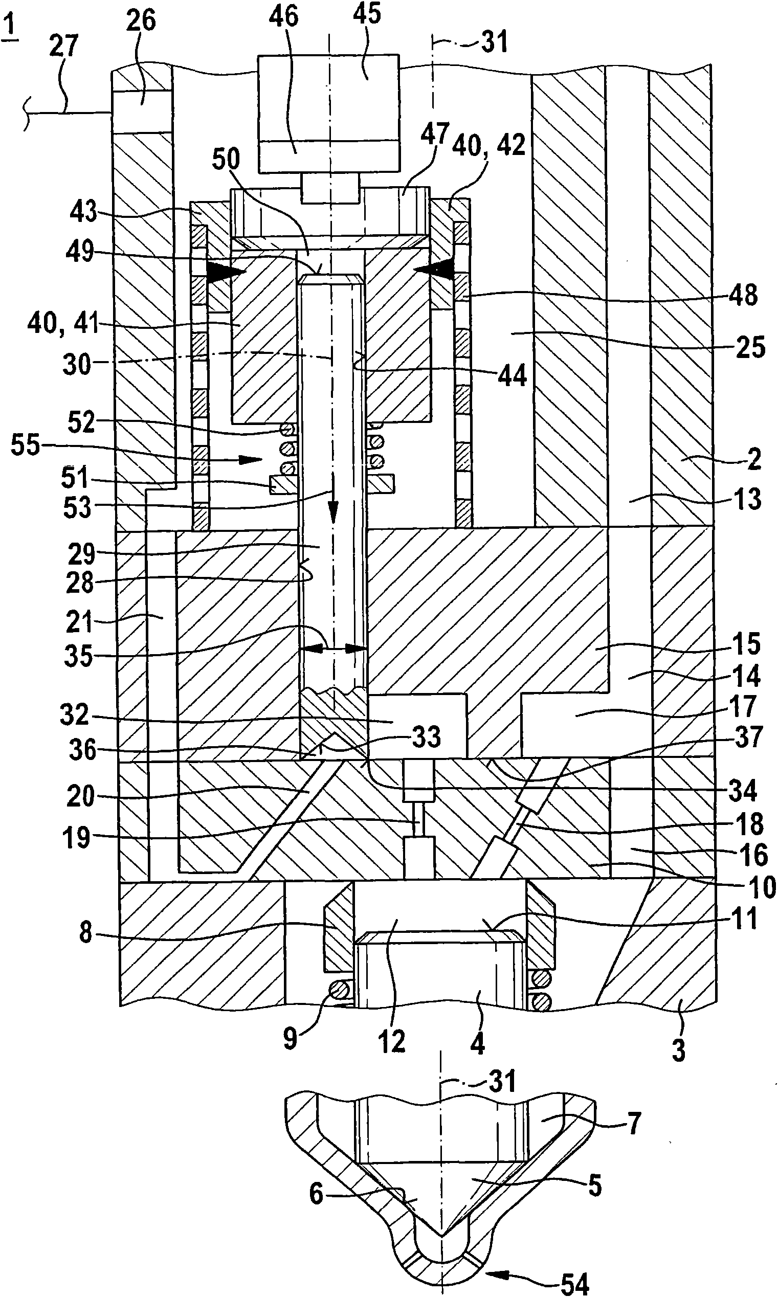
[0012] figure 1 An exemplary embodiment of a fuel injector 1 according to the invention is shown in a schematic, schematic axial section. The fuel injection valve 1 can be used in particular as an injector of a fuel injection system for an air-compressed self-ignition internal combustion engine. A preferred application of the fuel injection valve 1 is in a fuel injection system with a common rail which supplies a plurality of fuel injection valves 1 with diesel fuel under high pressure. However, the fuel injector 1 according to the invention is also suitable for other applications.

[0013] The fuel injector 1 has a holding body 2 and a nozzle body 3 . The nozzle body 3 is connected to the holding body 2 in a suitable manner. A nozzle needle 4 is arranged in the nozzle body 3 . The nozzle needle 4 has a valve closing body 5 . The nozzle body 3 has a valve seat surface 6 adapted to the valve closing body 5 . The valve closing body 5 cooperates in a sealing manner with the...


PUM


Abstract

A fuel injection valve (1), in particular an injector of a fuel injection device for compressing-air and self-ignition type internal combustion engine, is provided with a control valve (55) operated by an actuator (45). The control valve includes a valve rod (29), a valve plate (15) and a throttle plate (10). The valve plate (15) includes a through hole (28), the valve rod (29) is guided in the through hole (28), and the valve plate is provided with a dead slot (32) connected with the through hole (28) at a side facing the throttle plate (10). The throttle plate (10) is provided with an outputthrottle valve (19) communicated with the dead slot (32) of the valve plate (15) and a passage (20) connected with a low pressure return part (26), and the passage may be closed by the valve rod (29). When the control valve is operated, the valve rod releases the connection of the output throttle vlave (19) of the throttle plate (10) and the passage (20) of the throttle plate (10) by the dead slot (32) of the valve plate (15). Thereby, it is possible to implement pressure balance of the control valve (55). Furthermore, the valve plate (15) may have high component strength.

Description

technical field [0001] The invention relates to a fuel injection valve for a fuel injection system of an internal combustion engine. The invention relates in particular to the field of injectors for fuel injection systems of compressed-air, self-igniting internal combustion engines. Background technique [0002] A fuel injector with a pressure-balanced control valve is known from DE 10 2006 021 741 A1. The known injector serves to inject fuel into a combustion chamber of an internal combustion engine, wherein an injection valve element for opening or closing at least one nozzle opening is controlled by a control valve. In this case, the control valve releases or closes the connection from the control chamber to the fuel return. This will be achieved in such a way that a closing element is placed in the seat or releases the seat. A hole is formed in the closing element, in which a pin is accommodated, wherein the diameter of the hole corresponds substantially to the diamet...

Claims


Application Information

Patent Timeline
IPC IPC(8): F02M47/02
CPCF02M47/027F02M51/0603F02M63/004
Inventor M·吉翁特克
Owner ROBERT BOSCH GMBH
Why Eureka
Eureka Blog
Learn More