

Thermostatic valve
- Summary
- Abstract
- Description
- Claims
- Application Information
AI Technical Summary
Benefits of technology
Problems solved by technology
Method used
Image

Examples
Embodiment Construction
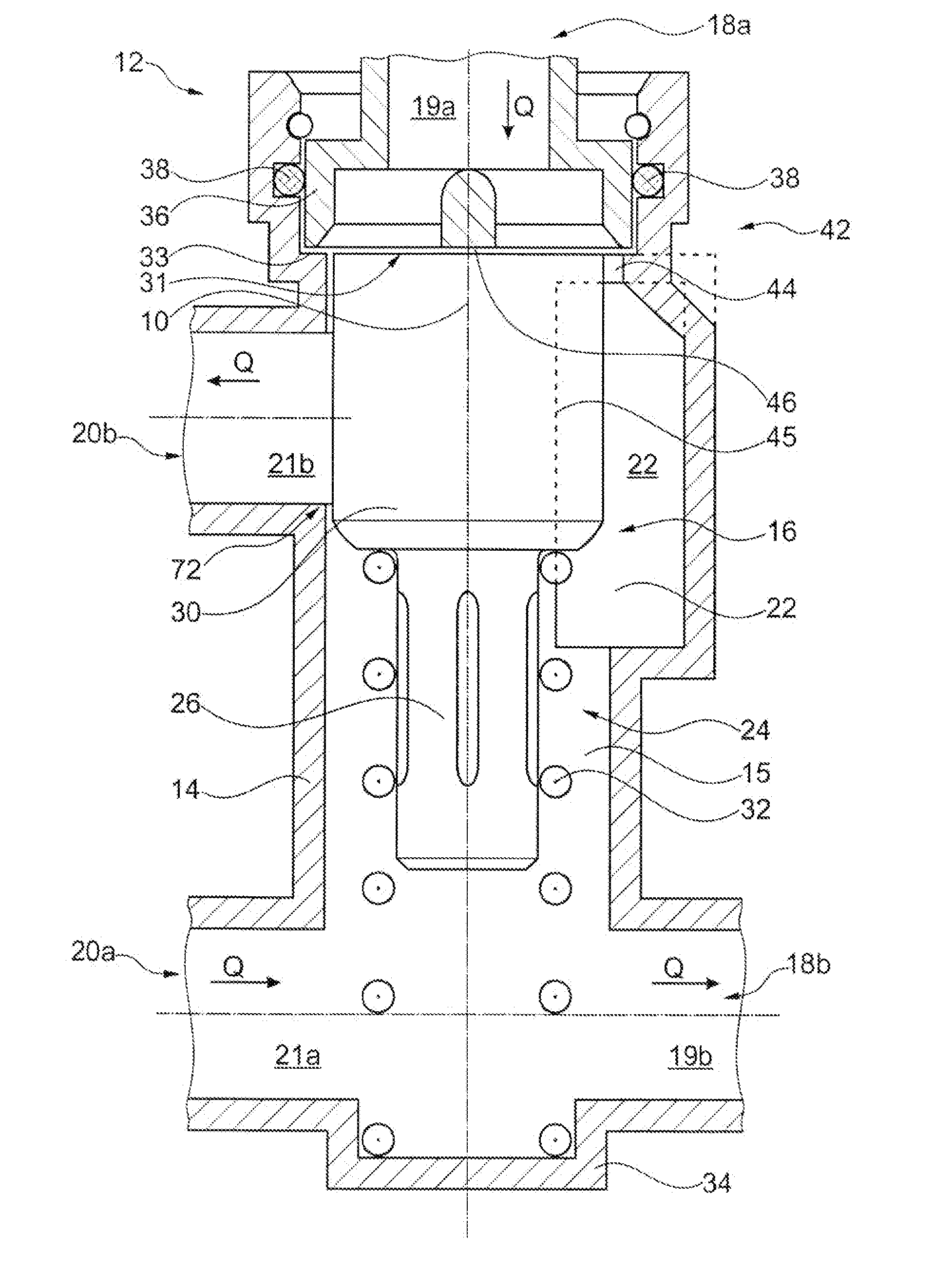
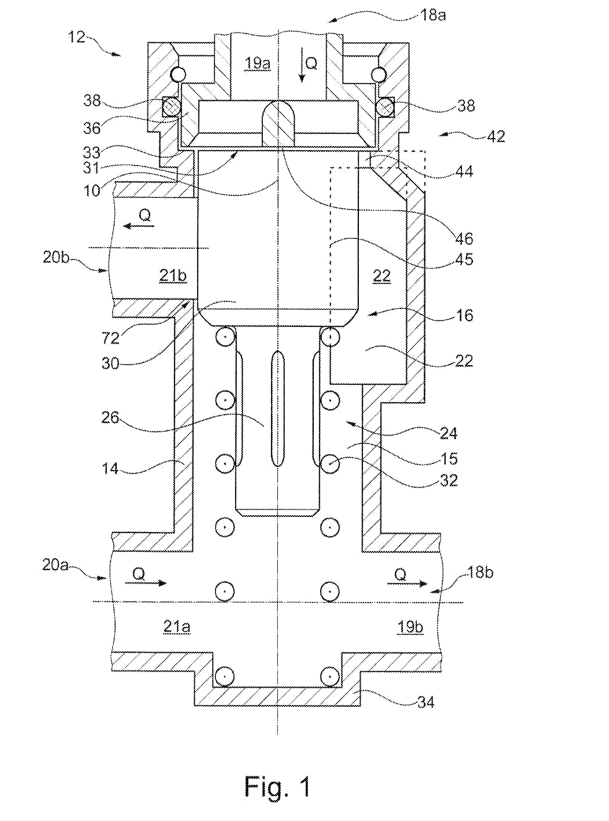
[0031]FIG. 1 shows a thermostatic valve 12 in a schematic sectional view along the central axis 10 with a one-piece thermostatic valve housing 14 with a thermostatic working element 16 arranged in an intake opening 15. The thermostatic valve 12 is shown in an idle mode and shows a travel of 0 mm. The thermostatic valve 12 is can be designed as a 4 / 2 directional valve and has a first inlet connection 18a to a first inlet port 19a and a second inlet connection 20a to a second inlet port 21a for a medium, for example, a fluid, which can flow into the thermostatic valve 12 coming from a heat source. Furthermore the thermostatic valve 12 has a first outlet connection 18b to a first outlet port 19b, and a second outlet connection 20b to a second outlet port 21b for the medium, for example, fluid. The flow of the medium (inlet medium flow, outlet medium flow) is marked each with a “Q” and an arrow indicating the direction. The connections 18a and 18b can be connected with an installation r...
PUM
 Abstract
Description
Claims
Application Information