[0006] In an HPSEM, the sample that is to be investigated is placed in an
atmosphere of a gas having a pressure typically between 0.1
Torr (13 Pa) and 50
Torr (7000 Pa), and more typically between 1
Torr (130 Pa) and 10 Torr (1,300 Pa) whereas in a conventional SEM the sample is located typically in a vacuum of about 10−6 Torr (1.3×10⁻⁶ mbar). Unlike a conventional SEM, an HPSEM can readily form electron-optical images of moist or non-conducting samples, such as biological samples, plastics,
ceramic materials and glass fibers, which would be difficult to image under the typical vacuum conditions of a conventional SEM. The HPSEM allows samples to be maintained in their
natural state, without being subjected to the disadvantageous effects of
drying, freezing or
vacuum coating, which are normally necessary in studies of such samples using conventional SEMs. The
gaseous atmosphere of an HPSEM
sample chamber provides inherent charge
neutralization, that is, the dissipation of
surface charge that accumulates on a non-conductive sample as a result of
irradiation. Dissipating
surface change increases resolving power of the
microscope.
[0007] The
gaseous atmosphere in an HPSEM also makes improved detection means possible. In an HPSEM, the liberated secondary electrons that move in the direction of the secondary electron detector will collide en
route with gas molecules in their path. This collision will result in the liberation of new electrons, referred to as “
daughter electrons,” from the gas molecules. The
daughter electrons will also move in the direction of the secondary electron detector. In their turn, these newly liberated
daughter electrons will again collide with other gas molecules, and so forth, so that an amplification of the secondary electron
signal occurs. The term secondary electron is used to include daughter electrons and reflected primary beam electrons, was well as electrons emitted directly from the sample. The greater the distance that the secondary electrons travel to the secondary electron detector, the greater the number of collisions that will occur between secondary electrons and gas molecules and so the greater the amplification achieved. On the other hand, it is desirable that the primary beam path through the pressurized
sample chamber be as short as possible because the gas molecules present scatter the primary beam electrons.
[0008] Japanese patent publication 5-174768(A) describes an HPSEM wherein the primary beam from the
particle source is focused on the sample by a magnetic immersion lens. The immersion lens consists of a
magnetic dipole having poles located on opposite sides of the sample. The
magnetic field will cause the secondary electrons liberated from the sample to follow a
helical path on their way to the detector. It is claimed that in this way, the distance traversed by the secondary electrons is increased, so that the
collision probability increases proportionately and the
amplification factor of the detection apparatus increases.
[0009] In the configuration described in JP5-174768(A) the electrons follow a
helical path around an axis that extends parallel to a
magnetic field. The distance traversed by the electron from the sample to the detector is directly dependent upon the distance between the detector and the sample in the direction of the
magnetic field. The detector
electrode should be therefore be located as high as possible above the sample, so as to achieve as large an
amplification factor as possible. Consequently, the distance traversed by the primary beam through the
gaseous atmosphere will also be large, and scattering of the primary beam will increase. An increased
amplification factor for the detection apparatus is thus achieved at the expense of the resolving power of the illustrated device.
[0010] An improved
environmental scanning electron microscope is described in U.S. Pat. No. 6,972,412 for “Particle-Optical Device and Detection Means,” to Scholtz et al. (Scholtz), which is hereby incorporated by reference and which is assigned to FEI Company, the assignee of the present invention. In the invention of Scholtz, a portion of the detector volume includes an
electric field having a component parallel to the magnetic field, and a portion has an
electric field having a component perpendicular to the magnetic field.
Secondary electrons are subjected to both axial oscillations (i.e., the Penning effect, also referred to as the “yo yo” effect), and radial oscillations (i.e., the “magnetron” effect). These oscillations greatly increase the secondary electron
path length, and hence the number of collisions with gas molecules, thereby increasing the amplification of the secondary electron
signal. The electric and magnetic fields are such to assure that a significant number of electrons in the detector space have sufficient energy to ionize the gas molecules.
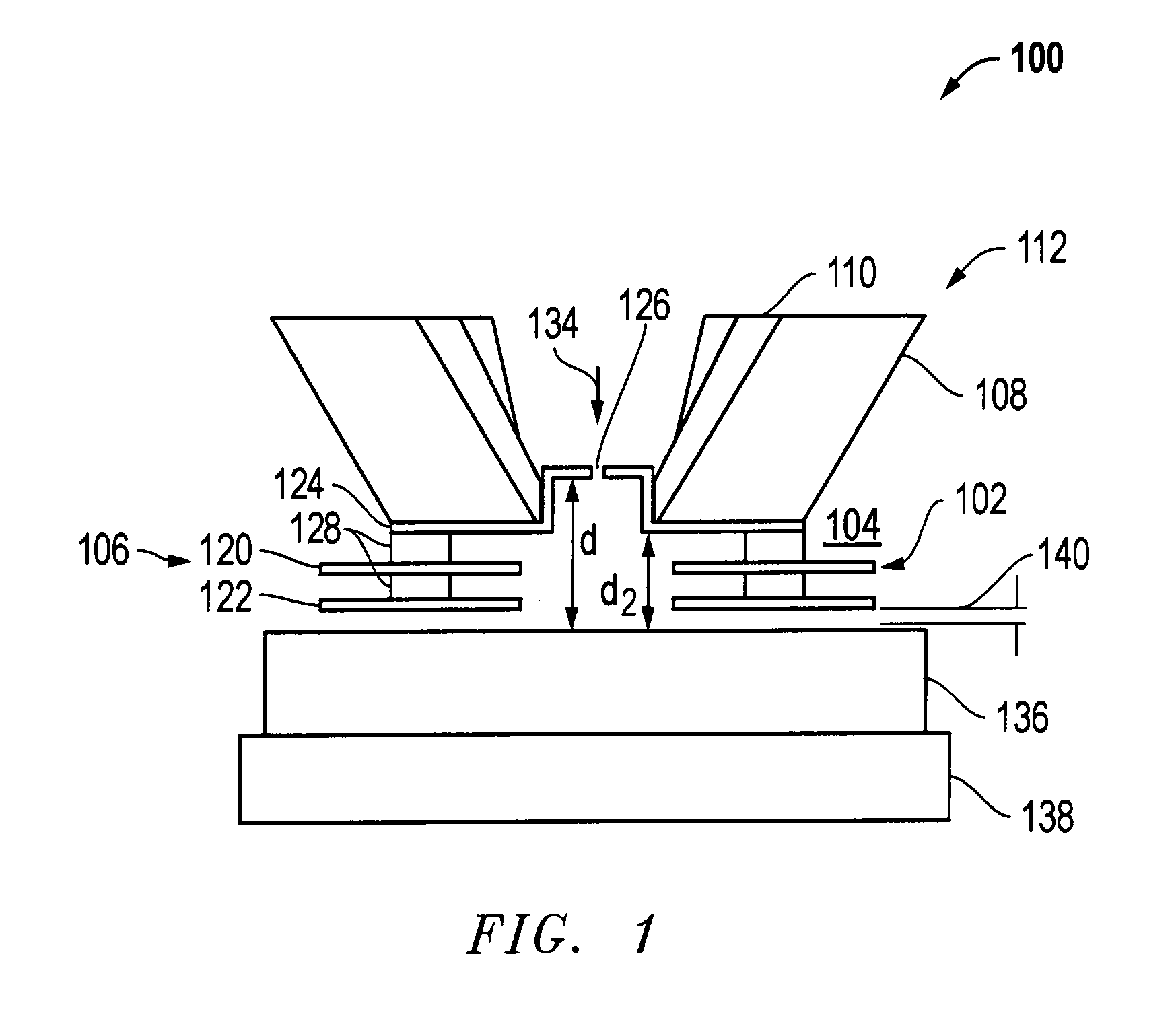
[0011]FIG. 1 shows an example of an improved HPSEM 100 using a detector 102 in accordance with the principals of Scholtz. In a
sample chamber 104, an
electrode assembly 106 is attached to the bottom of
pole piece support 108 that supports a
pole piece 110 of a lens 112. The
electrode assembly 106 includes an anode 120, an
ion trap 122, and a pressure limiting aperture electrode 124 having a hole that defines a pressure limiting aperture, PLA 126. Insulating spacers 128 separate the various electrodes. A primary electron beam 134 is directed through PLA 126 toward a sample 136 positioned on a movable sample stage 138. A gas is introduced into sample chamber 104 from a gas source 140.
Secondary electrons are emitted from the sample 136 upon
impact of the primary beam 134. The secondary electrons are accelerated toward the anode 120, and preferably undergo a combination of magnetron and penning oscillation. The secondary electrons lose energy as they collide with the gas molecules are eventually collected by the anode 120. Ionized gas molecules are collected by the
ion trap 122, the sample 136, and the PLA 126.
Secondary electrons have the distance, d, available between the sample and the PLA electrode to create additional electrons by collisions with gas molecule. In the detector described by Scholtz, the PLA is flush with the bottom of the
pole piece. The secondary electrons therefore have only the distance, d2, available to create additional electrons by collisions with gas molecule. By positioning the PLA inside the lens, the improved configuration provides additional detector space in which the gas can be ionized to amplify the secondary electron signal, without increasing the working distance, that is, the distance between the lens and the sample. Although positioning the PLA inside the lens provides additional detector space, there are still some disadvantages to the embodiment shown in FIG. 1.

